[7sj80_prot-lo-qvp, 1, en_US]
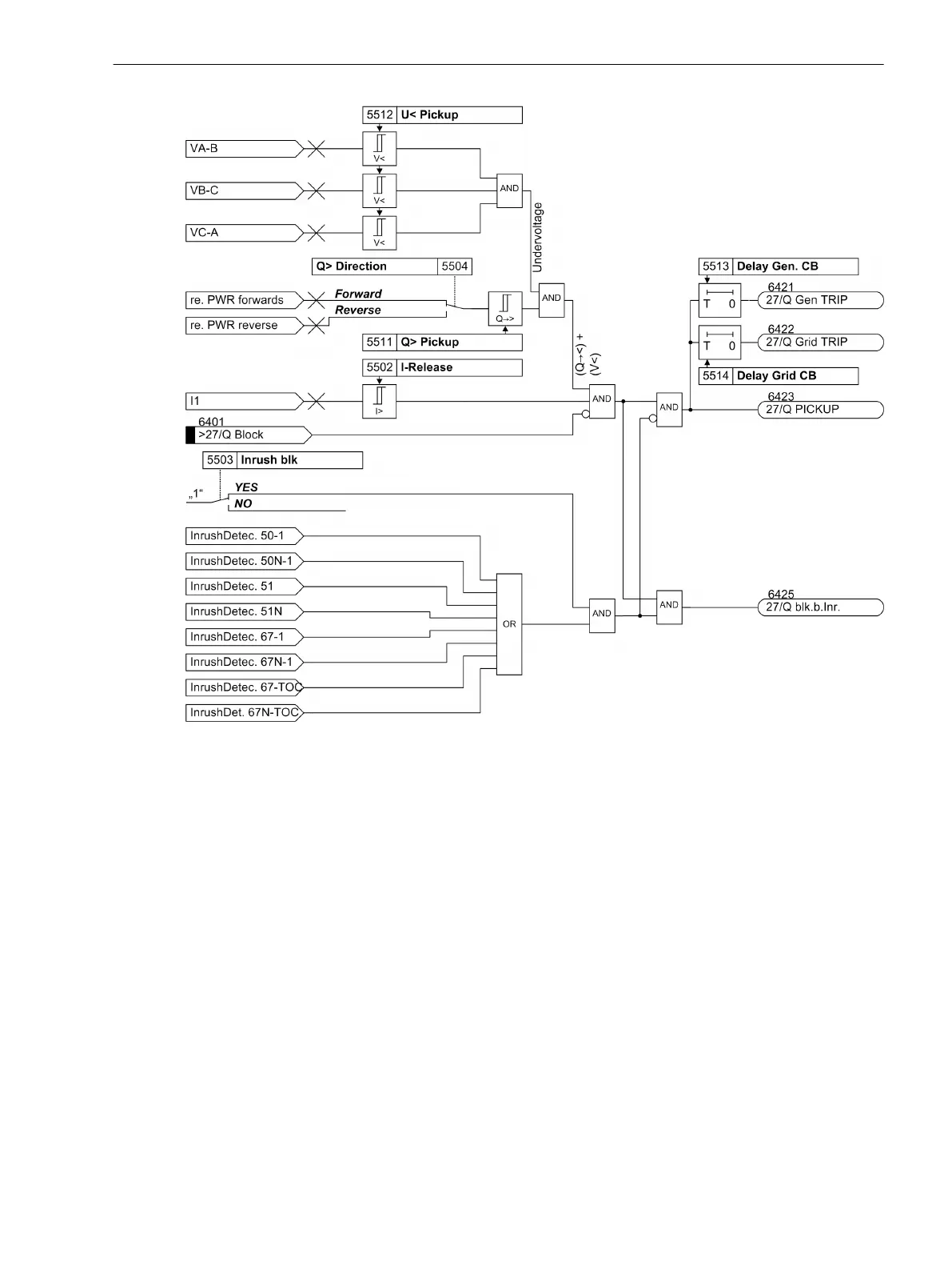
Figure 2-52
Logic diagram of the QU protection
Reconnection
The release for reconnecting the generating facility is given under the following conditions:
•
All 3 phase-to-phase voltages are above the parameterized threshold value.
•
The power system frequency is within the parameterized range.
•
The delay time of the protection function has elapsed. The delay time is started by the first trip signal of
any stage of the voltage or frequency protection.
The release criteria for reconnection can be set. The following parameters are used:
•
Threshold for the release voltage at the power system connection point
•
Frequency deviation in positive and negative direction
•
Reconnection release can be delayed by a settable time.
You also define whether the tripping of the circuit breaker at the power system connection point is included in
the formation of the release signal. The tripping of the protection stages of voltage and frequency protection
is always included.
The following figure shows the logic diagram of the QU protection for reconnection.
Functions
2.9 Undervoltage-controlled reactive power protection (27/Q)
SIPROTEC 4, 7SJ80, Manual 143
E50417-G1140-C343-A8, Edition 12.2017

 Loading...


