Monitoring of the Transformer Circuits
Open circuits or short circuits in the secondary circuits of the current and voltage transformers, as well as
faults in the connections (important during commissioning!), are detected and reported by the device. The
measured quantities are periodically checked in the background for this purpose, as long as no system fault is
present.
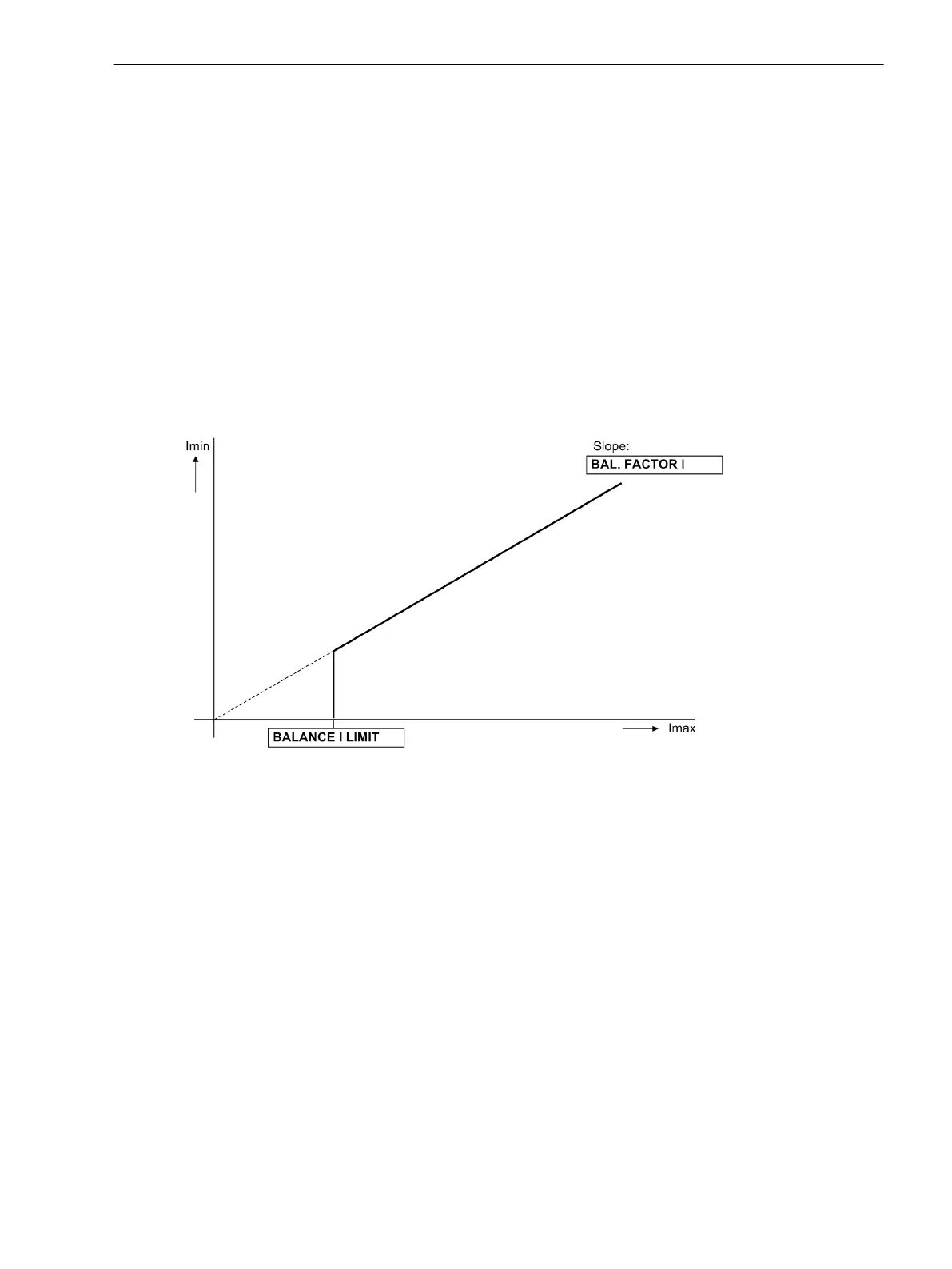
Current Symmetry
During normal system operation, symmetry among the input currents is expected. The monitoring of the
measured values in the device checks this balance. The smallest phase current is compared to the largest
phase current. Asymmetry is detected if | Ιmin | / | Ιmax | < BAL. FACTOR I as long as Ιmax > BALANCE I
LIMIT is valid.
Thereby Ιmax is the largest of the three phase currents and Imin the smallest. The symmetry factor BAL.
FACTOR I (address 8105) represents the allowable asymmetry of the phase currents while the limit value
BALANCE I LIMIT (address 8104) is the lower limit of the operating range of this monitoring (see
Figure 2-57). Both parameters can be set. The dropout ratio is about 97 %.
This fault is signalled after settable delay time with
Fail I balance
.
[stromsymmetrieueberwachung-020313-kn, 1, en_US]
Figure 2-57 Current symmetry monitoring
Voltage Symmetry
During normal system operation, balance among the voltages is expected. Since the phase-to-phase voltages
are insensitive to ground faults, the phase-to-phase voltages are used for balance monitoring. If the device is
connected to the phase-to-ground voltages, then the phase-to-phase voltages are calculated accordingly,
whereas, if the device is connected to phase-to-phase voltages and the displacement voltage V
0
, then the third
phase-to-phase voltage is calculated accordingly. From the phase-to-phase voltages, the device generates the
rectified average values and checks the balance of their absolute values. The smallest phase voltage is
compared with the largest phase voltage.
Asymmetry is recognized if
| V
min
| / | V
max
| < BAL. FACTOR V as long as | V
max
| > BALANCE V-LIMIT. Where V
max
is the highest of the
three voltages and V
min
the smallest. The symmetry factor BAL. FACTOR V (address 8103) represents the
allowable asymmetry of the conductor voltages while the limit value BALANCE V-LIMIT (address 8102) is
the lower limit of the operating range of this monitoring (see Figure 2-70). Both parameters can be set. The
dropout ratio is about 97%.
This fault is signalled after settable delay time with
Fail V balance
.
2.11.1.4
Functions
2.11 Monitoring Functions
SIPROTEC 4, 7SJ80, Manual 157
E50417-G1140-C343-A8, Edition 12.2017

 Loading...


