parameters that are common to all functions, i.e. not associated with a specific protection, control or moni-
toring function. The following section discusses these parameters.
Setting Notes
General
Some P.System Data 1 can be entered directly at the device. See Section 2.25 Notes on Device Operation
for more information regarding this topic.
In DIGSI double-click Settings to open the corresponding dialog box. In doing so, a dialog box with tabs will
open under P.System Data 1 where individual parameters can be configured. The following descriptions
are therefore structured according to these tabs.
Rated Frequency (Power System)
The nominal frequency of the system is set under the Address 214 Rated Frequency. The factory pre-
setting in accordance with the model need only be changed if the device will be employed for a purpose other
than that which was planned when ordering.
In the US device versions (ordering data position 10= C), parameter 214 is preset to 60 Hz. 214.
Phase Rotation (Power System)
Address 209 PHASE SEQ. is used to change the default phase sequence (A B C for clockwise rotation) if
your power system permanently has an anti-clockwise phase sequence (A C B. A temporary reversal of rota-
tion is also possible using binary inputs (see Section 2.21.2 Setting Notes).
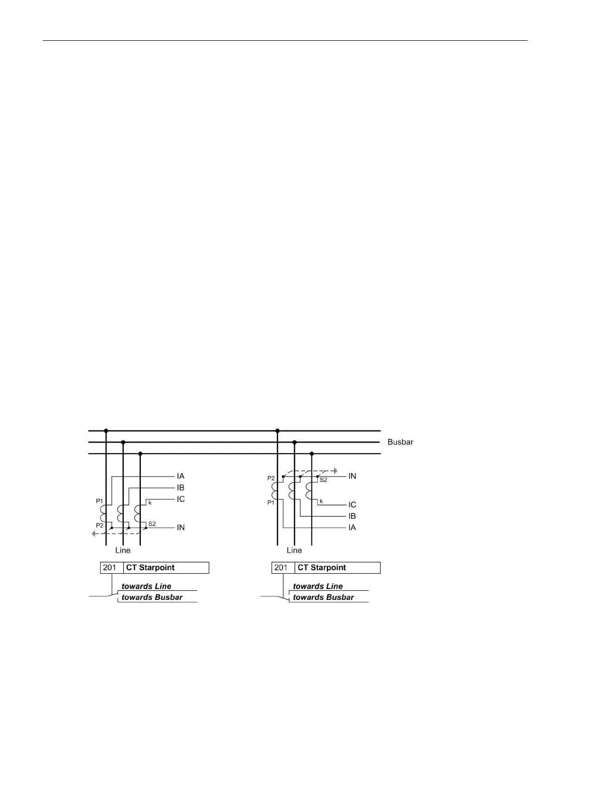
Polarity of Current Transformers (Power System)
At address 201 CT Starpoint, the polarity of the wye-connected current transformers is specified (the
following figure applies accordingly to two current transformers). This setting determines the measuring
direction of the device (forward = line direction). Changing this parameter also results in a polarity reversal of
the ground current inputs Ι
N
or Ι
NS
.
[polung-stromwandler-020313-kn, 1, en_US]
Figure 2-2 Polarity of current transformers
Current Connection Ι4 (Power System)
Here, it is communicated to the device whether the ground current of the current transformer neutral point is
connected to the fourth current input (Ι
4
). This corresponds to the Holmgreen connection, (see connection
example in C Connection Examples). In this case, parameter 280 Holmgr. for Σi is set to YES. In all other
cases, even if the ground current of the own line is measured via a separate ground current transformer, enter
the setting NO. This setting exclusively affects the function “Current Sum Monitoring” (see Section
2.11.1 Measurement Supervision).
2.1.3.2
Functions
2.1 General
38 SIPROTEC 4, 7SJ80, Manual
E50417-G1140-C343-A8, Edition 12.2017
 Loading...


