[7sj6x-stromsummenueberw-20070315, 1, en_US]
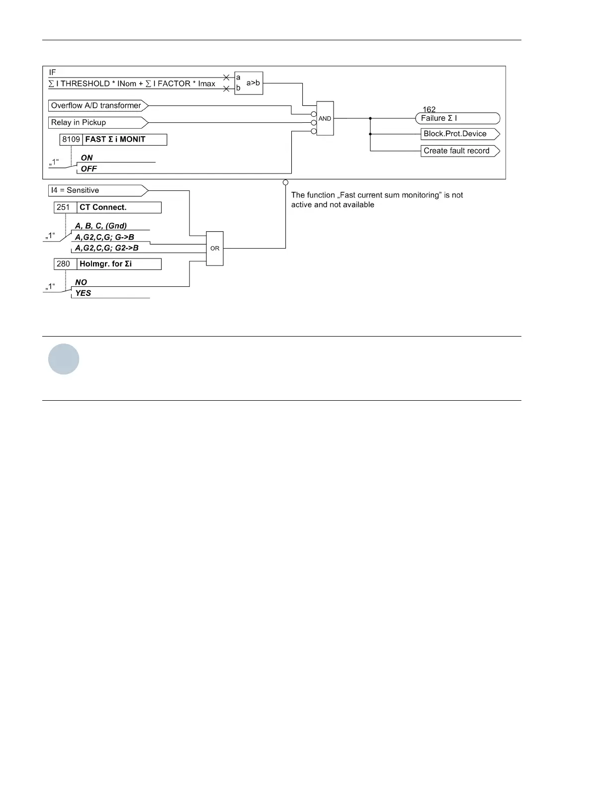
Figure 2-56 Logic Diagram of the fast current sum monitoring
NOTE
If the current input IN is configured as a sensitive transformer or if the connection mode A,G2,C,G; G-
>B or A,G2,C,G; G2->B was set for the current transformers at parameter 251 CT Connect., current
sum monitoring is not possible.
AD Transformer Monitoring
The digitized sampled values are being monitored in respect of their plausibility. If the result is not plausible,
message 181
Error A/D-conv.
is issued. The protection is blocked, thus preventing unwanted operation.
Furthermore, a fault record is generated for recording of the internal fault.
Software Monitoring
Watchdog
For continuous monitoring of the program sequences, a time monitor is provided in the hardware (hardware
watchdog) that expires upon failure of the processor or an internal program, and causes a complete restart of
the processor system.
An additional software watchdog ensures that malfunctions during the processing of programs are discov-
ered. This also initiates a restart of the processor system.
If such a malfunction is not cleared by the restart, an additional restart attempt is begun. After three unsuc-
cessful restarts within a 30 second window of time, the device automatically removes itself from service and
the red “Error” LED lights up. The readiness relay drops out and indicates „device malfunction“ with its normally
closed contact.
Offset Monitoring
This monitoring function checks all ring buffer data channels for corrupt offset replication of the analog/digital
transformers and the analog input paths using offset filters. Possible offset errors are detected using DC filters,
and the associated sampled values are corrected up to a specific limit. If this limit is exceeded, an indication is
generated (191
Error Offset
) and integrated into the warning group indication (160). As increased offset
values impair the measurements, we recommend sending the device to the OEM plant for corrective action
should this indication persist.
2.11.1.3
Functions
2.11 Monitoring Functions
156 SIPROTEC 4, 7SJ80, Manual
E50417-G1140-C343-A8, Edition 12.2017

 Loading...


