EasyManuals Logo

Siemens SIPROTEC 7SJ80 User Manual

Siemens SIPROTEC 7SJ80
562 pages
To Next Page IconTo Next Page
To Previous Page IconTo Previous Page
Page #238 background imageLoading...
Page #238 background image
[7sj62-64-svs-20081110, 1, en_US]
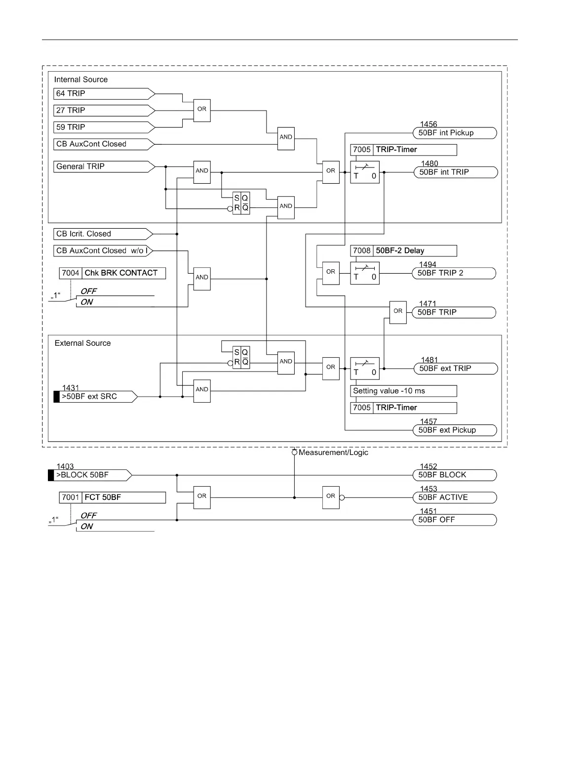
Figure 2-99
Logic diagram of the breaker failure protection
Setting Notes
General
Breaker failure protection is only effective and accessible if address 170 50BF is set to Enabled or enabled
w/ 3I0>. Setting Enabled considers the three phase currents for total current monitoring. Setting enabled
w/ 3I0> additionally evaluates the ground current or the negative sequence system when only one phase
current occurs.
If this function is not required, then Disabled is set. The function can be set to ON or OFF under address
7001 FCT 50BF.
2.17.2
Functions
2.17 Breaker Failure Protection 50BF
238 SIPROTEC 4, 7SJ80, Manual
E50417-G1140-C343-A8, Edition 12.2017

Table of Contents

Other manuals for Siemens SIPROTEC 7SJ80

Questions and Answers:

Question and Answer IconNeed help?

Do you have a question about the Siemens SIPROTEC 7SJ80 and is the answer not in the manual?

Siemens SIPROTEC 7SJ80 Specifications

General IconGeneral
Rated Frequency50/60 Hz
Rated Current1 A / 5 A
Operating Temperature-25°C to +55°C
Storage Temperature-40°C to +70°C
Current Transformer Inputs4
ApplicationProtection of feeders, motors, transformers, and generators
Rated Voltage100-240 V AC/DC
Communication ProtocolsIEC 61850, Modbus, DNP3, IEC 60870-5-103
DisplayGraphical LCD
MountingFlush mounting
Protection FunctionsOvercurrent, Earth fault
Communication InterfacesEthernet, RS485
HousingPlastic
WeightApprox. 1.5 kg

Related product manuals