[spannungssymmetrieueberwachung-020313-kn, 1, en_US]
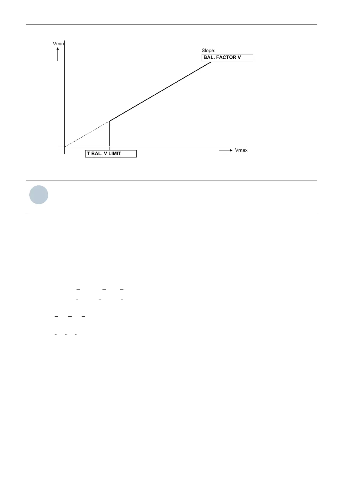
Figure 2-58 Voltage symmetry monitoring
NOTE
If the connection mode Vph-g, VSyn was set for the voltage transformers at parameter 213 VT
Connect. 3ph, voltage symmetry monitoring is not possible.
Phase Sequence of Voltage and Current
To detect swapped phase connections in the voltage and current input circuits, the phase sequence of the
phase-to-phase measured voltages and the phase currents are checked by monitoring the sequence of same
polarity zero crossing of the voltages.
Direction measurement with normal voltages, path selection for fault location, and negative sequence detec-
tion all assume a phase sequence of "abc". Phase rotation of measurement quantities is checked by verifying
the phase sequences. For that purpose, the phase-sequence monitoring uses the phase-to-phase voltages V
A2
,
V
B3
, V
C1
.
Voltages:
V
A2
before V
B3
vor V
C1
and
Currents: Ι
A
before Ι
B
before Ι
C
.
Verification of the voltage phase rotation is done when each measured voltage is at least
|
V
A2
|, |V
B3
|, |V
C1
| > 40 V
Verification of the current phase rotation is done when each measured current is at least:
|Ι
A
|, |Ι
B
|, |Ι
C
| > 0.5 Ι
N
.
For abnormal phase sequences, the messages
Fail Ph. Seq. V
or
Fail Ph. Seq. I
are issued, along
with the switching of this message
Fail Ph. Seq.
.
For applications in which an opposite phase sequence is expected, the protective relay should be adjusted via
a binary input or the respective parameter PHASE SEQ. (address 209). If the phase sequence is changed in
the relay, phases B and C internal to the relay are reversed, and the positive and negative sequence currents
are thereby exchanged (see also Section 2.21.2 Setting Notes). The phase-related messages, malfunction
values, and measured values are not affected by this.
Measurement Voltage Failure Detection
Requirements
The measuring voltage failure detection function - referred to as “Fuse Failure Monitor” (FFM) - only operates if
parameter 213 VT Connect. 3ph is set to Van, Vbn, Vcn or Vab, Vbc, VGnd. With all other voltage
transformer connection modes, FFM is not operative.
2.11.1.5
Functions
2.11 Monitoring Functions
158 SIPROTEC 4, 7SJ80, Manual
E50417-G1140-C343-A8, Edition 12.2017

 Loading...


