i
A
, i
B
, i
C
, i
N
, i
Ns
and v
A
, v
B
, v
C
, v
A2
, v
B3
, v
C1
, v
N
, v
X
, v
ph-n
, v
SYN
(voltages depending on connection) are sampled at intervals of 1.0 ms (at 50 Hz) and stored in a revolving
buffer (20 samples per cycle). In the event of a fault, the data are recorded for a set period of time, but not for
more than 5 seconds. A maximum of 8 faults can be recorded in this buffer. The fault record memory is auto-
matically updated with every new fault, so no acknowledgment for previously recorded faults is required. In
addition to protection pickup, the recording of the fault data can also be started via a binary input or via the
serial interface.
Functional Description
The data of a fault event can be read out via the device interface and evaluated with the help of the SIGRA 4
graphic analysis software. SIGRA 4 graphically represents the data recorded during the fault event and also
calculates additional information from the measured values. Currents and voltages can be presented either as
primary or as secondary values. Signals are additionally recorded as binary tracks (marks), e.g. "pickup", "trip".
If port B of the device has been configured correspondingly, the fault record data can be imported by a central
controller via this interface and evaluated. Currents and voltages are prepared for a graphic representation.
Signals are additionally recorded as binary tracks (marks), e.g. "pickup", "trip".
The retrieval of the fault data by the central controller takes place automatically either after each protection
pickup or after a tipping.
If device parameter 651 ParEN100(LC)blk is set to ON, you can also read out fault records via port A (see
Section 2.1.2.2 Setting Notes).
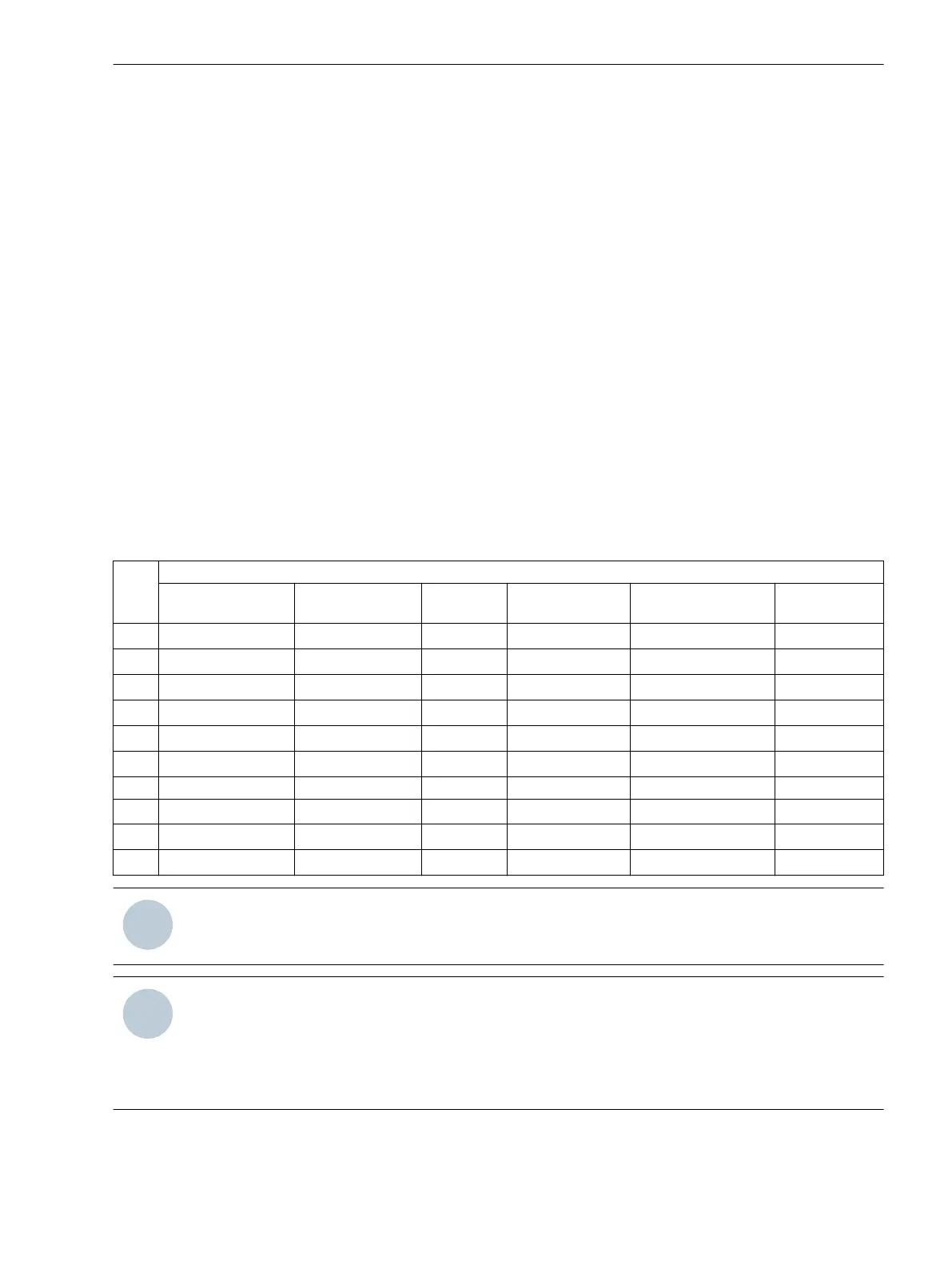
Depending on the selected type of connection of the voltage transformers (address 213 VT Connect. 3ph),
the following measured values are recorded in the fault record:
Voltage connection
Van, Vbn, Vcn Vab, Vbc,
VGnd
Vab, Vbc Vab, Vbc, Vx Vab, Vbc, VSyn Vph-g, VSyn
v
AB
yes yes yes yes yes
v
BC
yes yes yes yes yes
v
CA
yes yes yes yes yes
v
A
yes yes
v
B
yes yes
v
C
yes yes
v yes
v
en
yes yes
v
SYN
yes yes
v
x
yes
NOTE
The signals used for the binary tracks can be allocated in DIGSI.
NOTE
If one of the current transformer connection types A,G2,C,G; G->B or A,G2,C,G; G2->B has been
selected via parameter 251 CT Connect., the ground current Ι
N2
measured with the second current trans-
former is indicated under track Ι
N
. The ground current detected by the fourth current transformer is indi-
cated under track Ι
Ns
.
2.1.4.1
Functions
2.1 General
SIPROTEC 4, 7SJ80, Manual 47
E50417-G1140-C343-A8, Edition 12.2017
 Loading...


