If the displacement voltage is calculated, then:
3 · V
0
= V
A
+ V
B
+ V
C
If the displacement voltage is directly applied to the device, then V
0
is the voltage at the device terminals. It is
not affected by parameter Vph / Vdelta (address 206).
Pickup performed by the displacement voltage can be delayed (64-1 DELAY) for tripping.
It is important to note that the total trip-command time then consists of the displacement voltage measure-
ment time (about 50 ms) plus the pickup delay time 64-1 DELAY.
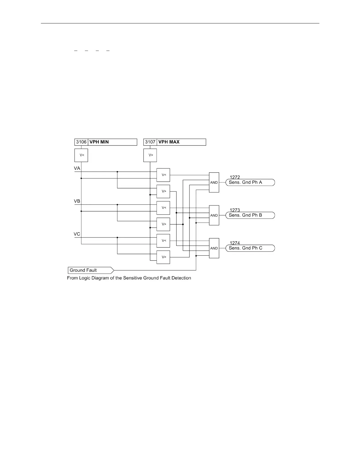
After the voltage element picks up due to detection of a displacement voltage, the grounded phase is identi-
fied, if possible. To do this, the individual phase-to-ground voltages are measured. Of course, this is only
possible if three phase-to-ground voltages are obtained from voltage transformers connected in a grounded
wye configuration. If the voltage magnitude for any given phase is below the setting value V
Ph min
, that phase
is detected as the grounded phase as long as the remaining phase-to-ground voltages are simultaneously
above the setting value V
Ph max
.
[7sj6x_erdschlussbehaftete_phase-150502-kn, 1, en_US]
Figure 2-73 Determination of Ground-faulted Phase
Current Elements
There are two current elements. Both elements operate directionally, whereby the tripping zones can be set
individually for each element (see margin heading “Tripping Area”). Both current elements are provided with a
definite time characteristic. Two current/time elements are used for ground fault protection. Analog to the
time overcurrent protection function, the overcurrent element is named 50Ns-1 PICKUP and 50Ns-1
DELAY and the high-set element 50Ns-2 PICKUP and 50Ns-2 DELAY.
The pickup of the definite time overcurrent protection can be stabilized by the configured dropout delay time
(address 3121 50Ns T DROP-OUT).
Tripping Area
The U0/I0-ϕ characteristic is illustrated as a sector in the U0/I0 phasor diagram (see Figure 2-74). This sector
corresponds to the tripping area. If the cursor of the ground current is in this sector, the function picks up.
The tripping area is defined via several parameters: Via the angle ϕ (parameter 3154 50Ns-1 Phi or 3151
50Ns-2 Phi), the center of the zone with reference to the displacement voltage V
0
is set. Via the angle Δϕ
(parameter 3155 50Ns-1 DeltaPhi or 3152 50Ns-2 DeltaPhi), the zone is extended to both sides of the
center.
Functions
2.12 Ground Fault Protection 64, 67N(s), 50N(s), 51N(s)
SIPROTEC 4, 7SJ80, Manual 179
E50417-G1140-C343-A8, Edition 12.2017

 Loading...


