The zone is further limited downwards by minimum values of the displacement voltage and ground current.
These settable threshold values must be exceeded in order to be picked up.
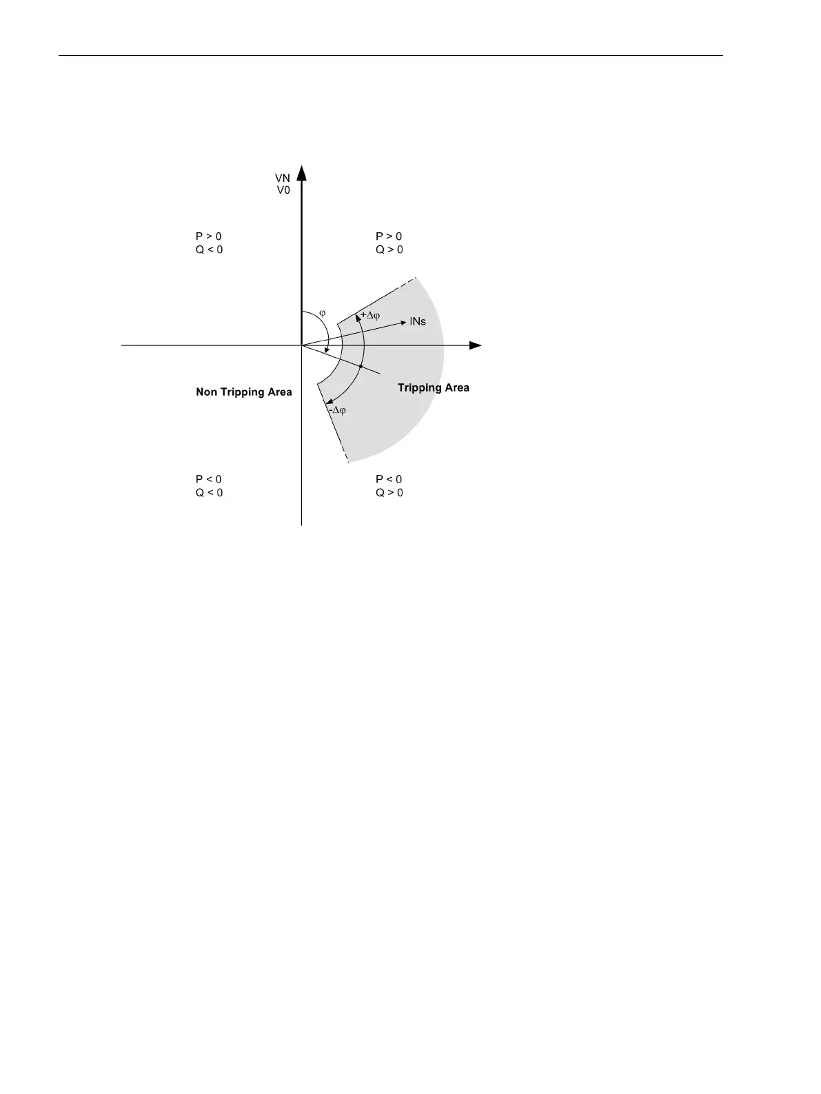
Negative angle settings turn the tripping area in the “inductiv” direction, i.e. ground current inductive
compared to ground voltage.
[enel-character, 1, en_US]
Figure 2-74
Tripping range of V0-Ι0-φ characteristic
Logic
The following figure illustrates the activation criteria of the sensitive ground fault protection. The operational
mode of the ground fault detection can be set under address 3101.
If set to ON, tripping is possible and a fault log is generated.
If set to ON with GF log, tripping is possible, a fault log and a ground fault log are generated.
If set to Alarm Only, tripping is not possible and only a ground fault log is generated.
The pickup of the displacement voltage V
0
or pickup of the 50Ns-2 element or pickup of the 50Ns-1 or 51Ns
element start the ground fault recording. As the pickup of the element drops out, fault recording is terminated
(see the following logic diagrams).
The entire function can be blocked under the following conditions:
•
A binary input is set,
•
the Fuse Failure Monitor or the voltage transformer protection breaker pick up.
Switching off or blocking means that measurement is deactivated. Therefore, time delays and pickup
messages are reset.
All elements can be blocked individually via binary inputs. In this case pickup and, if possible, direction and
grounded phase will still be reported, however, tripping does not take place since the time elements are
blocked.
To support the commissioning, a message is issued if the current and voltage threshold of an element is
exceeded but the ground fault phasor is not inside of the trip range.
Functions
2.12 Ground Fault Protection 64, 67N(s), 50N(s), 51N(s)
180 SIPROTEC 4, 7SJ80, Manual
E50417-G1140-C343-A8, Edition 12.2017

 Loading...


