[fohochimpp-1a-20120514, 1, en_US]
Please bear in mind that when choosing a higher pickup value Ι
pu
, the resistance must be decreased and, in
doing so, power loss will increase significantly.
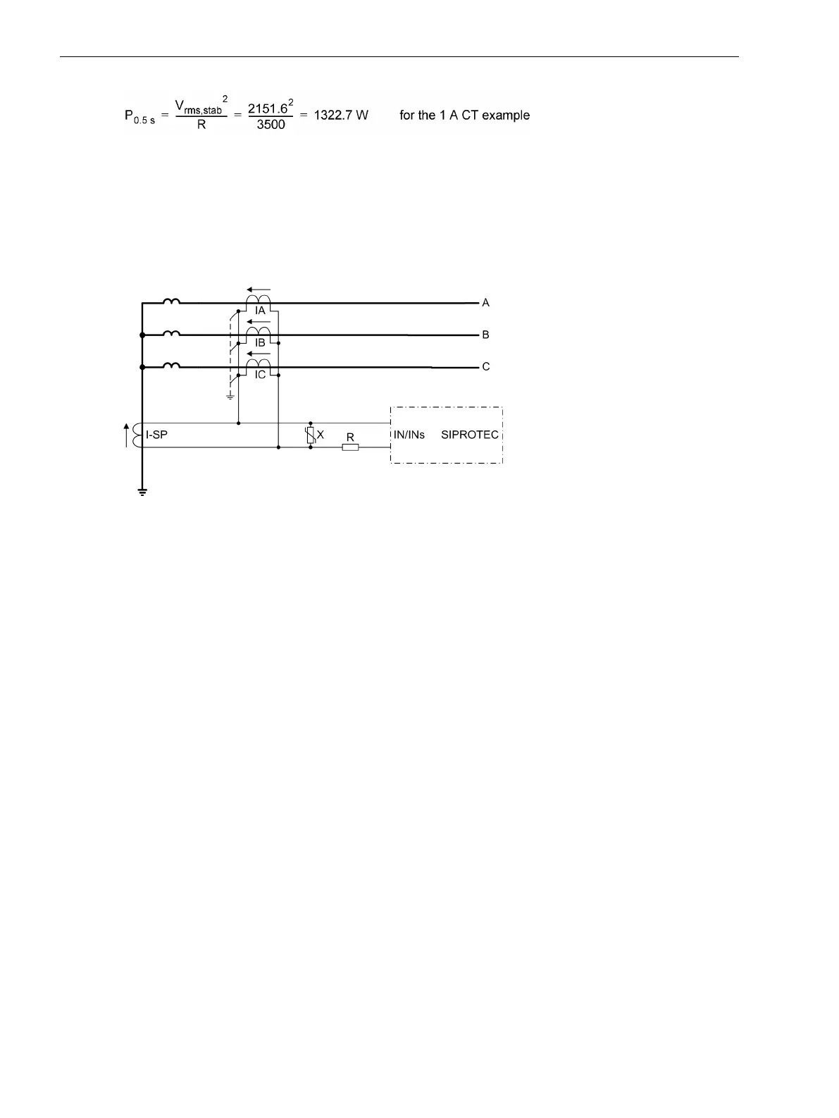
The varistor B (see following figure) must be dimensioned such that it remains high-resistive until reaching
knee-point voltage, e.g.
approx. 100 V for 5 A CT,
approx. 500 V for 1 A CT.
[sj6x-ueb-einph-hochimpedanz3-141103, 1, en_US]
Figure 2-43 Connection diagram of the ground fault differential protection according to the high-impe-
dance principle
Even with an unfavorable external circuit, the maximum voltage peaks should not exceed 2 kV for safety
reasons
If performance makes it necessary to switch several varistors in parallel, preference should by given to types
with a flat characteristic to avoid asymmetrical loading. therefore recommend the following types from
METROSIL:
600A/S1/S256 (k = 450, β = 0.25)
600A/S1/S1088 (k = 900, β = 0.25)
The pickup value (0.1 A or 0.05 A in the example) is set in address 2706 50 1Ph-1 PICKUP in the device.
The 50-2 element is not required (address 2703 50 1Ph-2 PICKUP = ∞ ).
The trip command of the protection can be delayed via address 2707 50 1Ph-1 DELAY. Normally, such
delay is set to 0.
If a higher number of CTs is connected in parallel, e.g. as busbar protection with several feeders, the magnet-
izing currents of the transformers connected in parallel cannot be neglected anymore. In this case, the
magnetizing currents at half the knee-point voltage (corresponds to the setting value) have to be summed up.
These magnetizing currents reduce the current through the resistor R. Therefore the actual pickup value will
be correspondingly higher.
Application as Tank Leakage Protection
The use as tank leakage protection requires that a sensitive input transformer is available at the device input
Ι
NS
. In this case, only the pickup value for single phase overcurrent protection is set at the 7SJ80 device for the
current at input Ι
NS
.
The tank leakage protection is a sensitive overcurrent protection which detects the leakage current between
the isolated transformer tank and ground. Its sensitivity is set in address 2706 50 1Ph-1 PICKUP. The 50-2
element is not required (address 2703 50 1Ph-2 PICKUP = ∞ ).
The trip command of the element can be delayed in address 2707 50 1Ph-1 DELAY. It is normally set to 0.
Functions
2.5 Single-Phase Overcurrent Protection
120 SIPROTEC 4, 7SJ80, Manual
E50417-G1140-C343-A8, Edition 12.2017

 Loading...


