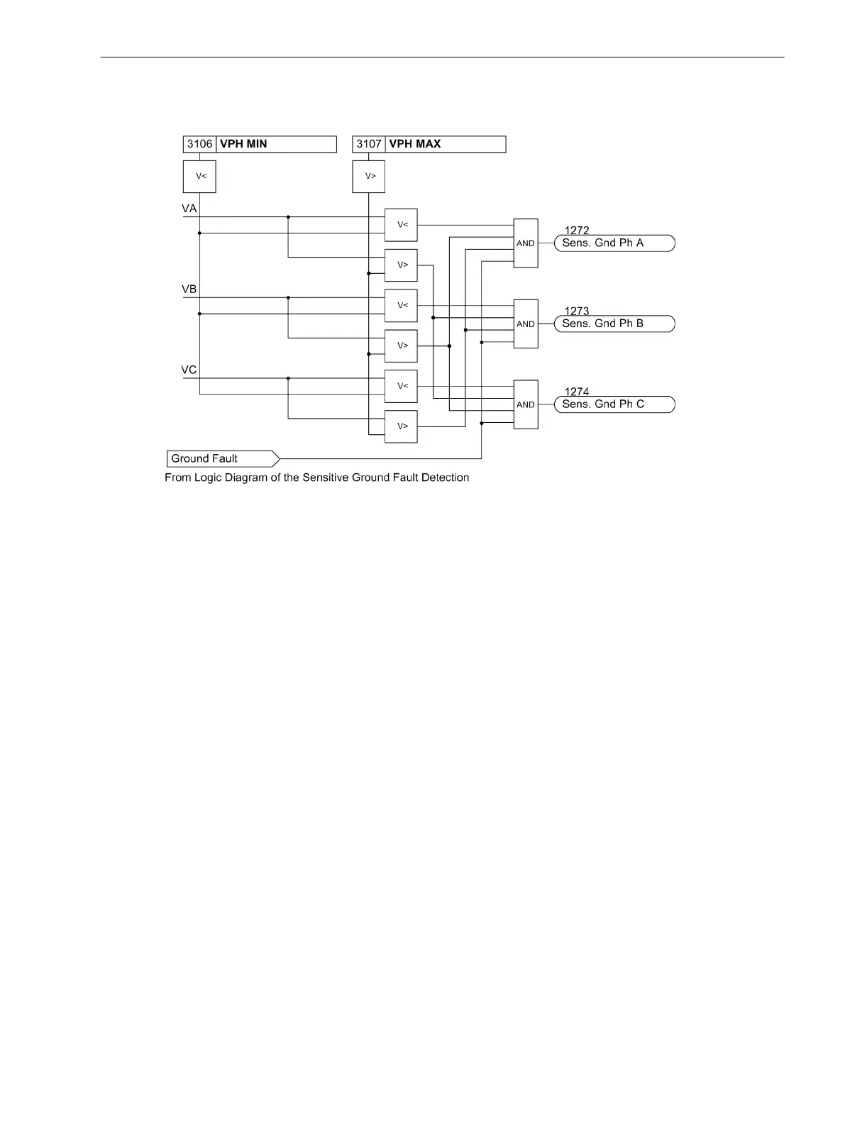
below the set threshold VPH MIN, that phase is detected as the grounded phase as long as the remaining
phase-to- ground voltages exceed the set threshold VPH MAX.
[7sj6x_erdschlussbehaftete_phase-150502-kn, 1, en_US]
Figure 2-67 Determination of Grounded Phase
Current Elements
The current elements for ground faults operate with the magnitudes of the ground current. It is sensible to
employ them only where the magnitude of the ground current can be used to specify the ground fault. This
may be the case on grounded systems (solid or low-resistance) or on electrical machines which are directly
connected to the busbar of an isolated power system, when in case of a network ground fault the machine
supplies only a negligible ground fault current across the measurement location, which must be situated
between the machine terminals and the network, whereas in case of a machine ground fault the higher
ground fault current produced by the total network is available. Ground current protection is mostly used as
backup protection for high resistance ground faults in solid or low resistance grounded systems when the
main fault protection does not pickup.
For ground current detection,a two-element current/time characteristic can be set. Analogeous to the time
overcurrent protection, the high-set current stage is designated as 50Ns-2 PICKUP and 50Ns-2 DELAY and
is provided with a definite time characteristic. The overcurrent element may be operated with either a definite
time delay (50Ns-1 PICKUP and 50Ns-1 DELAY) or with a user-defined Curve (51Ns PICKUP and
51NsTIME DIAL). The characteristics of these current elements can be configured. Each of these elements
may be directional or non-directional.
The pickup of the definite time overcurrent protection can be stabilized by the configured dropout delay time
(address 3121 50Ns T DROP-OUT).
The dropout delay only works if the current stage is operated independently of the voltage stage. Parameter
3130 PU CRITERIA is set to Vgnd OR INs.
Determination of Direction
When determining the sensitive ground fault direction it is not the current value that is crucial, but the part of
the current which is perpendicular to a settable directional characteristic (axis of symmetry). As a prerequisite
for determining the direction, the displacement voltage V
0
must be exceeded as well as a configurable current
part influencing the direction (active or reactive component).
The following figure illustrates an example using a complex vector diagram in which the displacement voltage
V
0
is the reference magnitude of the real axis. The active part 3Ι0
real
of current 3Ι0 is calculated with reference
Functions
2.12 Ground Fault Protection 64, 67N(s), 50N(s), 51N(s)
SIPROTEC 4, 7SJ80, Manual 173
E50417-G1140-C343-A8, Edition 12.2017

 Loading...


