The entire function can be blocked under the following conditions:
•
A binary input is set,
•
the Fuse Failure Monitor or the voltage transformer protection breaker pick up and parameter 3130 PU
CRITERIA is set to Vgnd AND INs,
•
the Fuse Failure Monitor or the voltage transformer protection breaker pick up and parameter 3130 PU
CRITERIA is set to Vgnd OR INs, and both current elements are in directional operation mode.
Switching off or blocking means that measurement is deactivated. Therefore, time delays and pickup
messages are reset.
All elements can be blocked individually via binary inputs. In this case pickup and, if possible, direction and
grounded phase will still be reported, however, tripping does not take place since the time elements are
blocked.
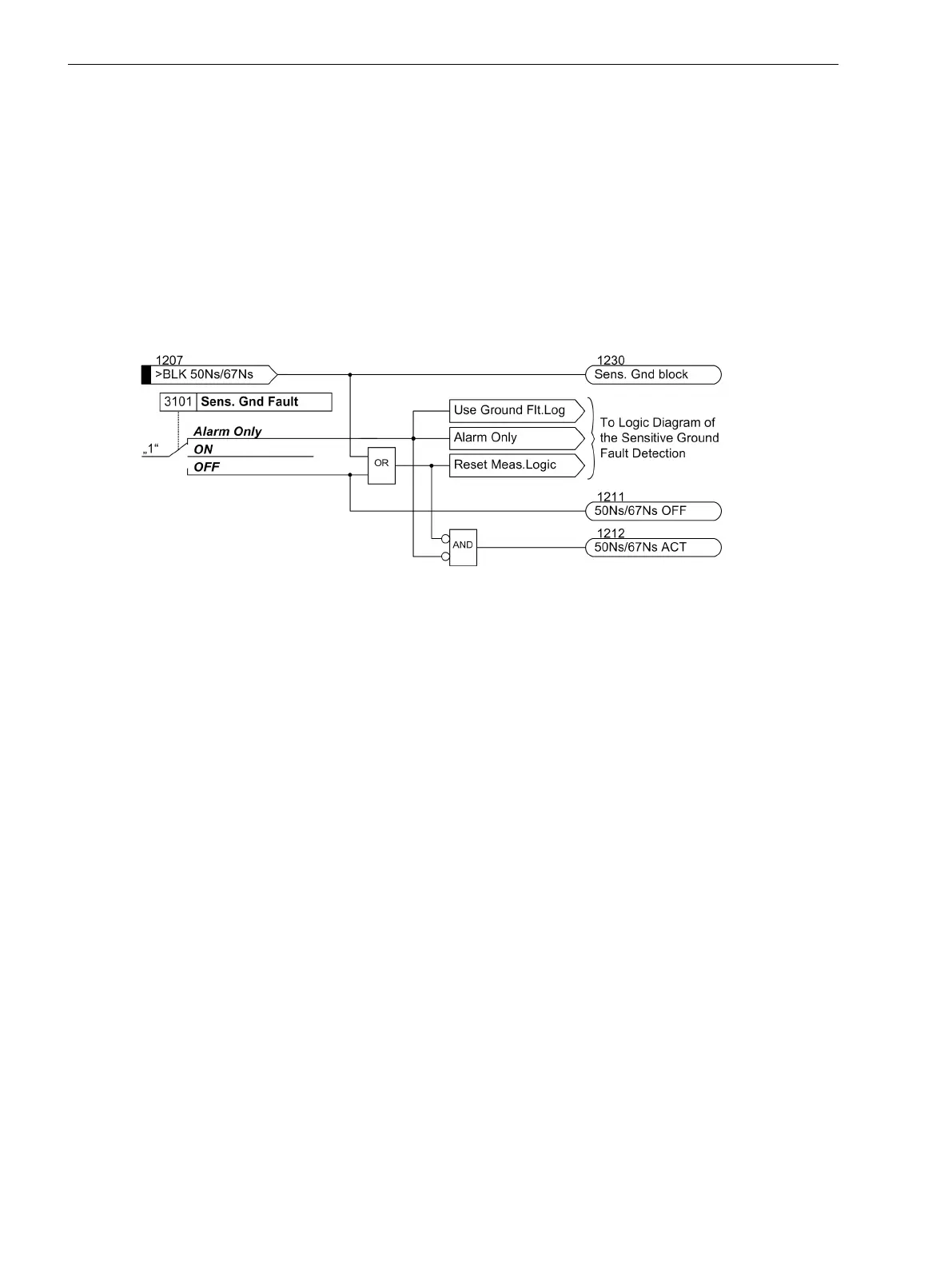
[7sj80-aktiv-cos-sin-empf-ef-070309, 1, en_US]
Figure 2-70 Activation of the sensitive ground-fault detection for cos-ϕ -/sin-ϕ measurement
Generation of a pickup message, for both current elements, is dependent on the direction selection for each
element and the setting of parameters 3130 PU CRITERIA. If the element is set to Non-Directional and
parameter PU CRITERIA = Vgnd OR INs, a pickup message is generated as soon as the current threshold is
exceeded, irrespective of the status of the V0 element. If, however, the setting of parameter PU CRITERIA is
Vgnd AND INs, the V
0
–element must have picked up also for non-directional mode.
However, if a direction is programmed, the current element must be picked up and the direction determina-
tion results must be present to generate a message. Once again, a condition for valid direction determination
is that the voltage element V
0
be picked up.
Parameter PU CRITERIA specifies, whether a fault is generated by means of the AND-function or the ORcom-
bination of displacement voltage and pickup of the ground current. The former may be advantageous if the
pickup setting of displacement voltage element V
0
was chosen to be very low.
Functions
2.12 Ground Fault Protection 64, 67N(s), 50N(s), 51N(s)
176 SIPROTEC 4, 7SJ80, Manual
E50417-G1140-C343-A8, Edition 12.2017

 Loading...


