Address 7134
DEADTIME 4: G
Dead time for the 4th reclosing attempt ground
Addresses 7236 to 7247,
7254, 7255, 7262, 7263
Cyclic control of the various protection functions by the 4th reclosing
attempt
Fifth to Ninth Reclosing Attempt
If more than four cycles are configured, the dead times set for the fourth cycle also apply to the fifth to ninth
cycle.
Blocking Three-Phase Faults
Regardless of which reclosing program is executed, automatic reclosing can be blocked for trips following
three-phase faults (address 7165 3Pol.PICKUP BLK). The pickup of all three phases for a overcurrent
element is the criterion required.
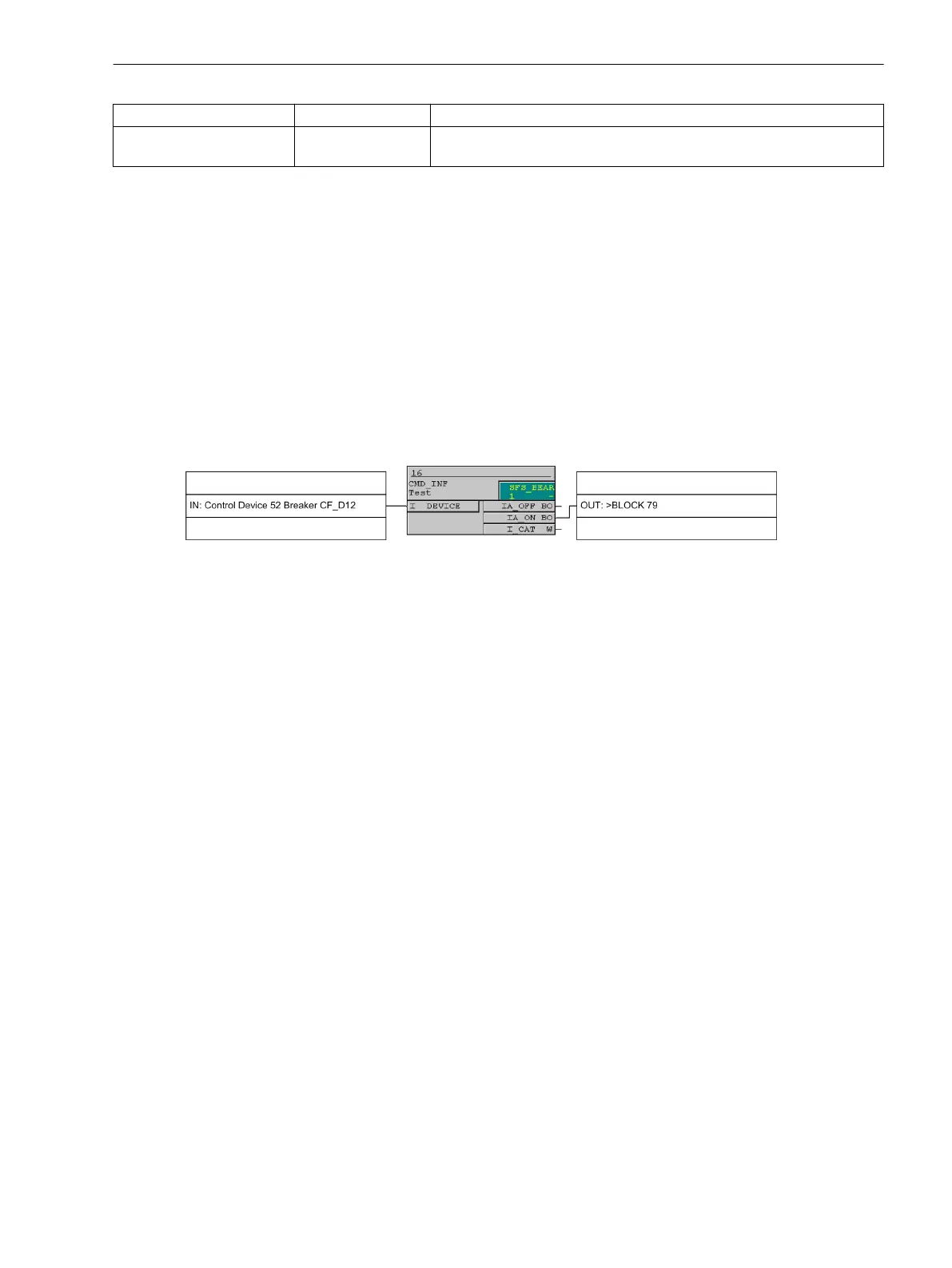
Blocking of Automatic Rreclosure via Internal Control
The automatic reclosure function can be blocked, if control commands are issued via the integrated control
function of the device. The information must be routed via CFC (interlocking task-level) using the CMD_Infor-
mation function block (see the following figure).
[blockierung-der-wiedereinschaltautomatik-26-06-02-kn, 1, en_US]
Figure 2-95 Blocking of the automatic reclose function using the internal control function
Zone Sequencing / Fuse Saving Scheme
At address 7140 ZONE SEQ.COORD., the zone sequencing feature can be turned ON or OFF.
If multiple reclosing operations are performed and the zone sequencing function is deactivated, only those
reclosing cycles are counted which the device has conducted after a trip command. If the zone sequencing
function is switched on, an additional sequence counter also counts such automatic reclosures which (in radial
systems) are carried out by relays connected on load side. This presupposes that the pickup of the 50-1/50N-1
elements drops out without a trip command being issued by a protection function starting the automatic
reclosing function. The parameters at addresses 7200 to 7263 (see paragraphs below at "Start and Blocking of
Automatic Reclosing by Protection Functions" and "Controlling Directional/Non-Directional Overcurrent Protec-
tion Elements via Cold Load Pickup") can thus be set to determine which protection elements are active or
blocked during what dead time cycles (for multiple reclosing attempts carried out by relays on the load side).
In the example shown in Figure "Zone sequencing with a fault occurring at Tap Line 5 and the busbar" (see
Figure 2-93) in the functional description, the zone sequencing was applied in the bus relay. Furthermore, as
from the second automatic reclosure, the 50-2 elements (also applicable to the 50-3 elements) must be
blocked, i.e. address 7214 bef.2.Cy:50-2 must be set to blocked T=∞. The zone sequencing of the
feeder relays is switched off but the 50-2 elements must also be blocked after the second reclosing attempt.
Moreover, it must be ensured that the 50-2 elements start the automatic reclosing function: Set address 7152
50-2 to Starts 79.
All settings of the 50-2 and 50-3 elements apply analogously to the 50N-2 and 50N-3 elements.
Controlling Overcurrent Protection Stages via Cold Load Pickup
The dynamic cold load pickup function provides a further alternative to control the protection via the auto-
matic reclosing function (see also Section 2.4 Dynamic Cold Load Pickup). This function contains the param-
eter 1702 Start Condition. It determines the starting conditions for the increased setting values of
current and time of the dynamic cold load pickup that must apply for directional and non-directional overcur-
rent protection.
If address 1702 Start Condition = 79 ready, the overcurrent protection always employs the increased
setting values if the automatic reclosing system is ready. The auto-reclosure function provides the signal 79
ready for controlling the cold load pickup. The signal 79 ready is always active if the auto-reclosing system
Functions
2.15 Automatic Reclosing System 79
SIPROTEC 4, 7SJ80, Manual 223
E50417-G1140-C343-A8, Edition 12.2017

 Loading...


