[synchro-fkt-querkuppl-061115, 1, en_US]
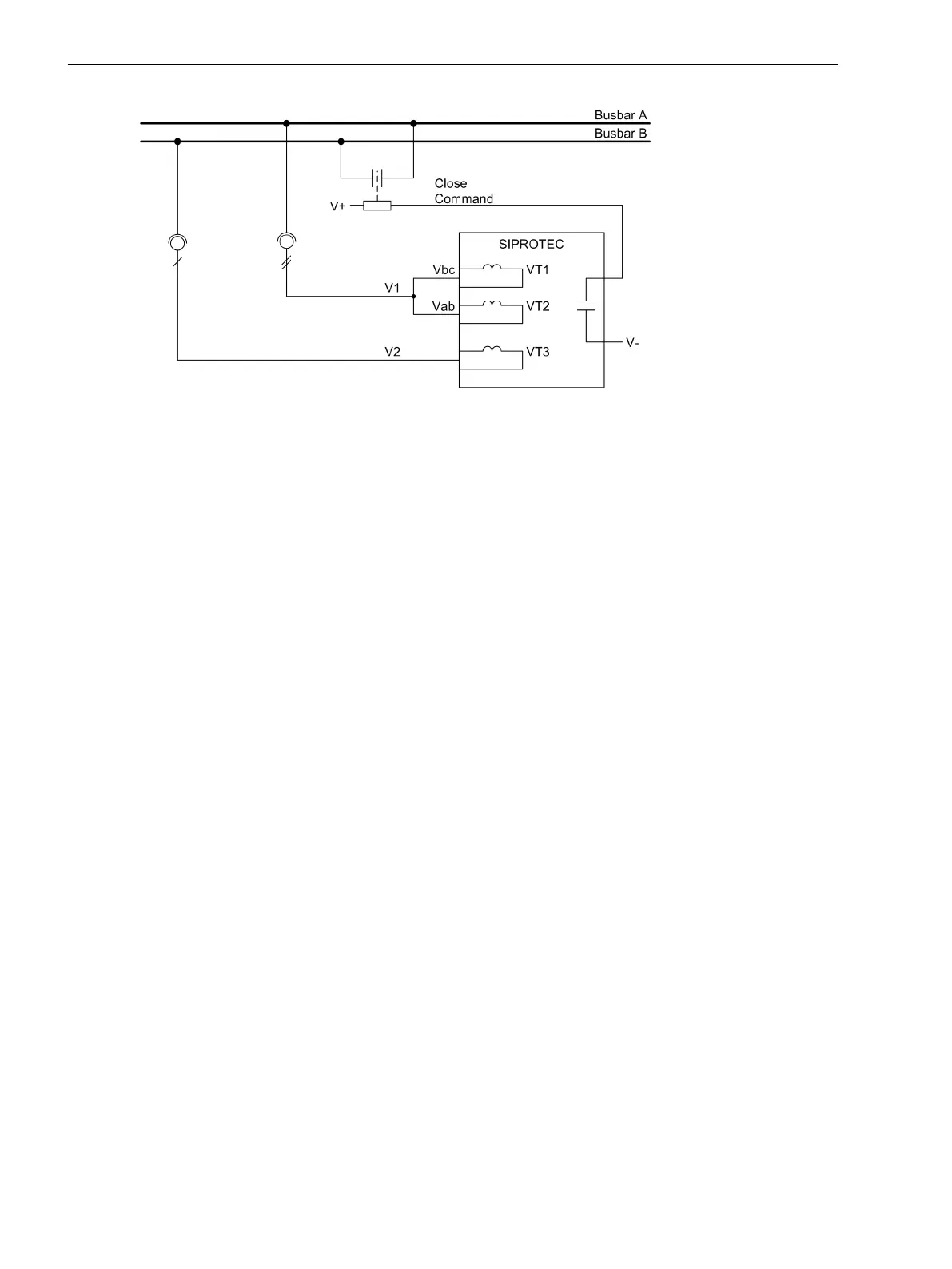
Figure 2-113 Cross coupling
The synchrocheck function of the 7SJ80 usually coordinates with the integrated automatic reclosing system
and the control function. Nevertheless, it is also possible to employ an external automatic reclosing system. In
such a case, the signal exchange between the devices is to be accomplished via binary inputs and outputs.
The configuration determines whether the synchrocheck is to be carried out only in the case of automatic
reclosing or only in the case of circuit breaker control or in both cases. It is also possible to configure different
release criteria for automatic reclosing or control closing. Synchronous connection is always accomplished via
the integrated control.
The release command for closing under satisfied synchronism conditions can be deactivated via parameter
6113 25 Synchron. For special applications, the deactivated closing release can, however, be activated via a
binary input (
>25 synchr.
) (see “De-energized Switching”).
Connection, Multi-phase
For comparing the two voltages, the synchrocheck function uses the reference voltage V
1
and an additional
voltage to be connected V
2
. For the multi-phase connection, set the P.System Data 1 at 213 Vab, Vbc,
VSyn. With this setting, the device is connected as open-delta connection and the phase-to-phase voltages V
AB
and V
BC
are used as reference voltage V
1
. The voltage to be synchronized V
2
is assigned to the single-phase
connection and may be any phase-to-phase voltage. The connected voltage is set at address 6123.
Furthermore, it should be noted that in the case of an open-delta connection, no zero voltage can be deter-
mined. In this case, the functions “Directional Ground Fault Detection” and “Fuse Failure Monitor (FFM)” must
be hidden or disabled. The function „Directional Overcurrent Protection Ground“ then works with the negative
sequence system values. Notes on the effects of the current transformer connection can be found in Section
2.1.3.2 Setting Notes, Table 2-1.
Connection, Single-phase
If there is only one phase-to-ground voltage available for the reference voltage V
1
, the device can be informed
of this fact via the P.System Data 1, address 213 Vph-g, VSyn. Also in this case the synchrocheck func-
tion can be fully applied. For the voltage to be synchronized V
2
, the same phase-to-ground voltage as for V
1
has to be connected.
Please note that some of the protection functions are restricted or do not work at all with this kind of connec-
tion. Notes on the effects of the current transformer connection can be found in Section 2.1.3.2 Setting Notes,
Table 2-1.
Functions
2.20 Synchrocheck
262 SIPROTEC 4, 7SJ80, Manual
E50417-G1140-C343-A8, Edition 12.2017

 Loading...


