•
System interlocking relies on the system data base in the substation or central control system.
•
Bay interlocking relies on the object data base (feedbacks) of the bay unit.
•
Cross-bay interlocking via GOOSE messages directly between bay units and protection relays (with
IEC61850: The inter-relay communication with GOOSE is performed via the EN100 module)
The extent of the interlocking checks is determined by the configuration of the relay. To obtain more informa-
tion about GOOSE, please refer to the SIPROTEC 4 System Description.
Switching objects that require system interlocking in a central control system are assigned to a specific param-
eter inside the bay unit (via configuration matrix).
For all commands, operation with interlocking (normal mode) or without interlocking (Interlocking OFF) can
be selected:
•
For local commands, by activation of "Normal/Test"-key switch,
•
For automatic commands, via command processing. by CFC and deactivated interlocking recognition,
•
For local / remote commands, using an additional interlocking disable command, via Profibus.
Interlocked / Non-Interlocked Switching
The configurable command checks in the SIPROTEC 4 devices are also called "standard interlocking". These
checks can be activated via DIGSI (interlocked switching/tagging) or deactivated (non-interlocked).
Deactivated interlock switching means the configured interlocking conditions are not checked in the relay.
Interlocked switching means that all configured interlocking conditions are checked within the command
processing. If a condition is not fulfilled, the command will be rejected by a message with a minus added to it
(e.g. “CO–”), immediately followed by a message.
The following table shows the possible types of commands in a switching device and their corresponding
annunciations. For the device the messages designated with *) are displayed in the event logs, for DIGSI they
appear in spontaneous messages.
Type of Command
Command Cause Message
Control issued Switching CO CO +/–
Manual tagging (positive / negative) Manual tagging MT MT+/–
Information state command, input blocking Input blocking ST ST+/– *)
Information state command, output blocking Output blocking ST ST+/– *)
Cancel command Cancel CA CA+/–
The "plus" appearing in the message is a confirmation of the command execution. The command execution
was as expected, in other words positive. The minus sign means a negative confirmation, the command was
rejected. Possible command feedbacks and their causes are dealt with in the SIPROTEC 4 System Description.
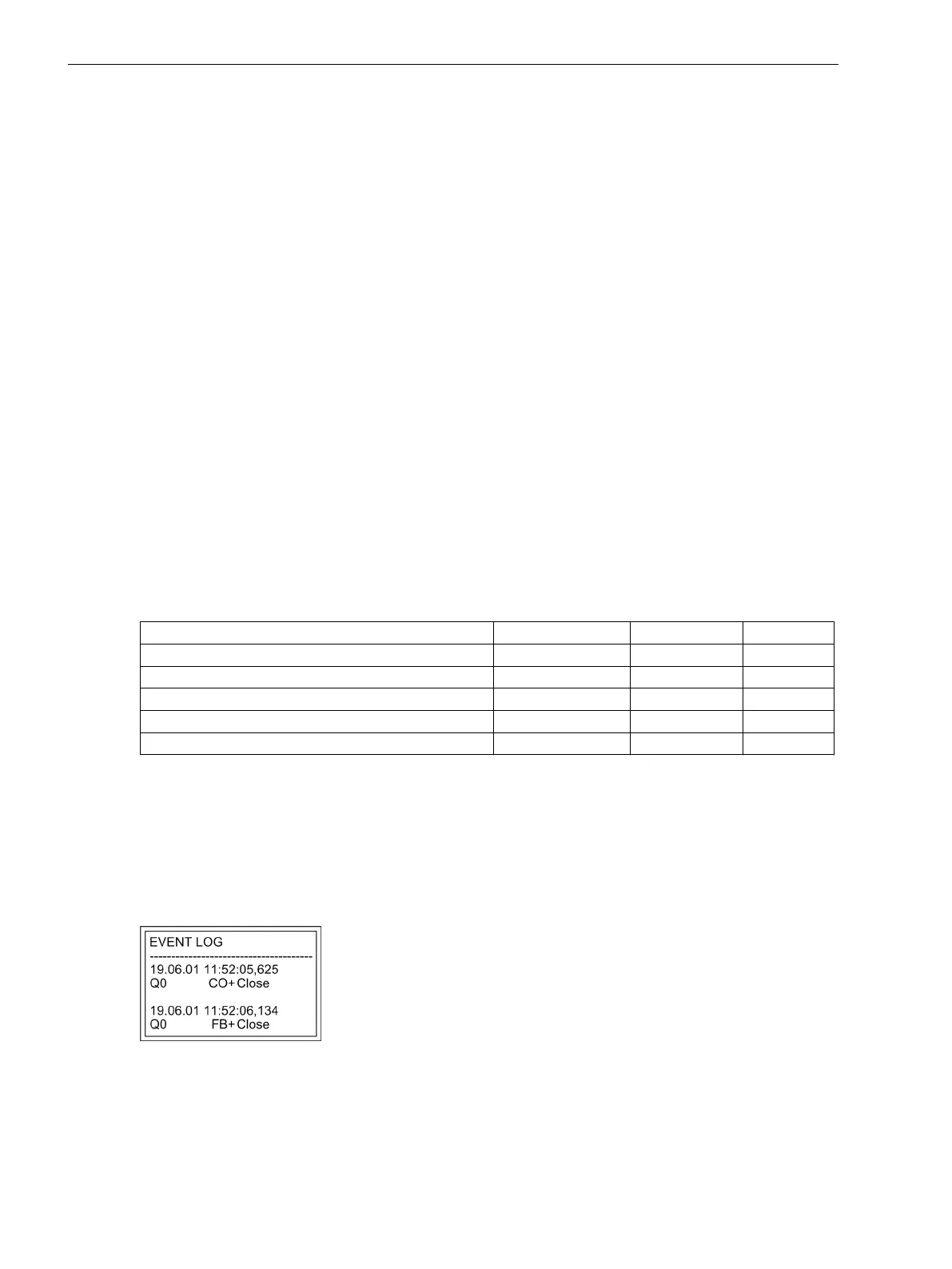
The following figure shows operational indications relating to command execution and operation response
information for successful switching of the circuit breaker.
The check of interlocking can be programmed separately for all switching devices and tags that were set with
a tagging command. Other internal commands such as manual entry or abort are not checked, i.e. carried out
independent of the interlocking.
[leistungsschalterbetriebsmeldung-020315-wlk, 1, en_US]
Figure 2-128 Example of an operational annunciation for switching circuit breaker 52 (Q0)
Standard Interlocking (default)
The standard interlockings contain the following fixed programmed tests for each switching device, which can
be individually enabled or disabled using parameters:
Functions
2.24 Breaker Control
302 SIPROTEC 4, 7SJ80, Manual
E50417-G1140-C343-A8, Edition 12.2017
 Loading...


