•
Two binary inputs must be dedicated to the purpose of changing setting groups when four groups are to
be switched. One binary input must be set for
>Set Group Bit0
, the other input for
>Set Group
Bit1
. If either of these input functions is not assigned, then it is considered as not controlled.
•
For the control of 2 setting groups one binary input is sufficient, namely
>Set Group Bit0
, since the
non-assigned binary input
>Set Group Bit1
is then regarded as not connected.
•
The control signals must be permanently active so that the selected setting group is and remains active.
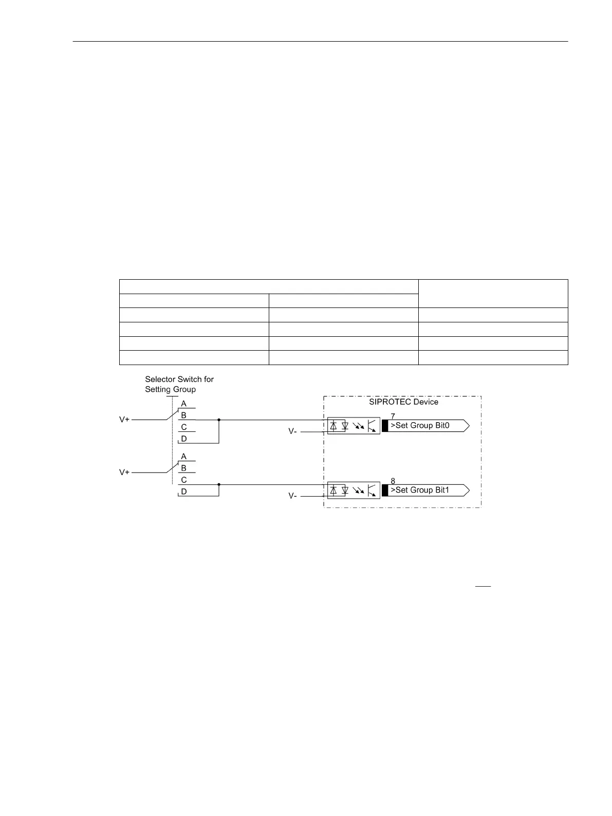
The following table shows the allocation of the binary inputs to the setting groups A to D and a simplified
connection diagram for the two binary inputs is illustrated in the following figure. The figure illustrates an
example in which both Set Group Bits 0 and 1 are configured to be controlled (actuated) when the associated
binary input is energized (high).
Where:
no = not energized or not connected
yes = energized
Table 3-1 Changing setting groups using binary inputs
Binary Input Active Group
>Param.Wahl1 >Param. Wahl2
no no Group A
yes no Group B
no yes Group C
yes yes Group D
[einstellgruppenumschaltung-ueber-binaere-160502-wlk, 1, en_US]
Figure 3-1 Connection diagram (example) for setting group switching using binary inputs
Trip Circuit Supervision 74TC
It must be noted that two binary inputs or one binary input and one bypass resistor R must be connected in
series. The pick-up threshold of the binary inputs must therefore be substantially below
half the rated control
DC voltage.
If one binary input is used, a bypass resistor R must be used (see following figure). The resistor R is inserted
into the circuit of the 52b circuit breaker auxiliary contact to facilitate the detection of a malfunction also
when the 52a circuit breaker auxiliary contact is open and the trip contact has dropped out. The value of this
resistor must be such that in the circuit breaker open condition (therefore 52a is open and 52b is closed), the
circuit breaker trip coil (52TC) is no longer energized and binary input (BI1) is still energized if the command
relay contact is open.
Mounting and Commissioning
3.1 Mounting and Connections
SIPROTEC 4, 7SJ80, Manual 313
E50417-G1140-C343-A8, Edition 12.2017

 Loading...


