[en100-lc_schraeg-20071107, 1, --_--]
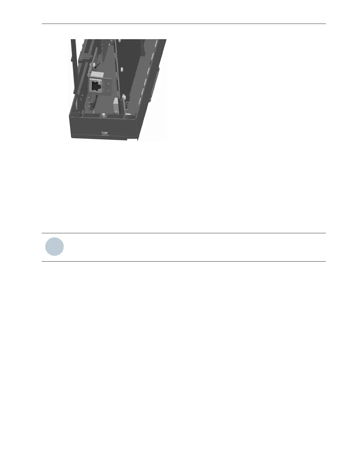
Figure 3-8 Installation of the Ethernet interface
Now, a SIPROTEC 4 communication module can be installed (see Section Installation or Replacement of a
SIPROTEC 4 Communication Module). Otherwise, the device can be reassembled again (see Section Reas-
sembly).
Installation or Replacement of a SIPROTEC 4 Communication Module
The following description assumes the normal case that a SIPROTEC 4 communication module which has not
yet been existing is retrofitted.
If a SIPROTEC 4 communication module has to be removed or replaced, the steps are to be performed in
reverse order.
NOTE
The installation can only be performed alone or after the installation of the Ethernet module.
The SIPROTEC 4 communication module is inserted via the large window in the plastic supporting plate. The
direction of insertion is not arbitrary. The module is held at its mounting bracket. The opposite end of the
module is inserted with the same orientation in the window opening, under the supporting plate and any
existing extension I/O. The module bracket is turned towards the Ethernet module locking latch at the
supporting plate. Thus, even the longest connection elements of the communication module can be moved in
this space between the lower supporting plate reinforcement and the locking latch in the direction of the
transformer module. The mounting bracket of the module is now drawn up to the stop in the direction of the
lower supporting plate reinforcement. Thus, the 60-pin plug connector on the module and the basic I/O board
are aligned on top of each other. The alignment has to be checked via the opening at the bottom of the rack.
Attach the module's mounting rail from the back side of the basic I/O using 2 M 2.5 screws.
Mounting and Commissioning
3.1 Mounting and Connections
SIPROTEC 4, 7SJ80, Manual 321
E50417-G1140-C343-A8, Edition 12.2017

 Loading...


