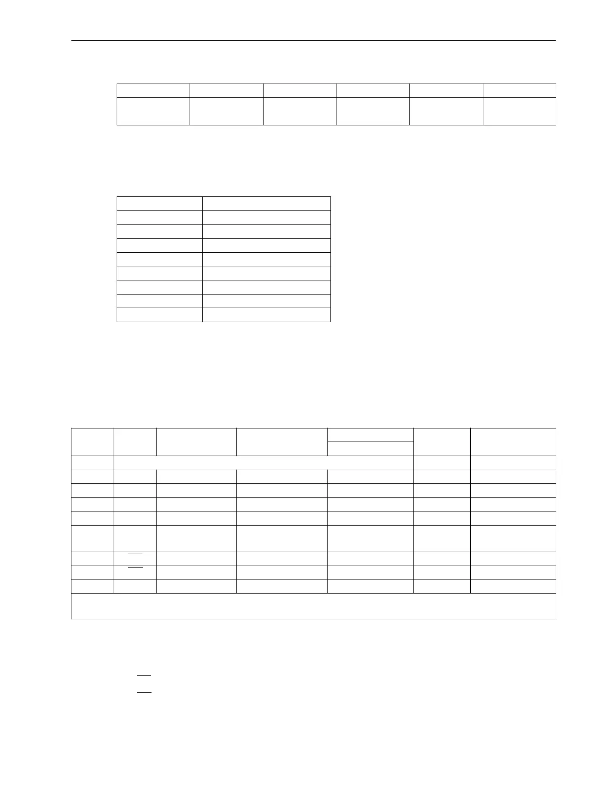
Table 3-2 Assignment of the USB socket
Pin-No. 1 2 3 4 Housing
USB VBUS
(unused)
D- D+ GND Shield
Connections at port A
If the interface is used for communication with the device, the data connection is to be checked.
Table 3-3 Assignment of the port A socket
Pin-No. Ethernet interface
1 Tx+
2 Tx-
3 Rx+
4 —
5 —
6 Rx-
7 —
8 —
Connections at port B
When a serial interface of the device is connected to a control center, the data connection must be checked. A
visual check of the assignment of the transmit and receive channels is important. With RS232 and fiber optic
interfaces, each connection is dedicated to one transmission direction. For that reason the data output of one
device must be connected to the data input of the other device and vice versa.
Table 3-4
Belegung der Buchsen Port B
Pin-No. RS232 RS485 Profibus DP, RS485 Modbus RS485 Ethernet
EN 100
IEC 60870–5–103
redundant
DNP3.0 RS485
1 Shield (electrically connected with shield shroud) Tx+ B/B’ (RxD/TxD-P)
2 RxD – – – Tx– A/A’ (RxD/TxD-N)
3 TxD A/A’ (RxD/TxD-N) B/B’ (RxD/TxD-P) A Rx+ –
4 – – CNTR-A (TTL) RTS (TTL level) — –
5 GND C/C’ (GND) C/C’ (GND) GND1 — –
6 – – +5 V ((max. load
<100 mA)
VCC1 Rx– –
7 RTS
–
1)
– – — –
8 CTS B/B’ (RxD/TxD-P) A/A’ (RxD/TxD-N) B — –
9 – – – – not available not available
1)
Pin 7 also carries the RTS signal with RS232 level when operated as RS485 interface. Pin 7 must therefore not be
connected!
With data cables, the connections are designated according to DIN 66020 and ISO 2110:
•
TxD = Data output
•
RxD = Data input
•
RTS = Request to send
•
CTS = Clear to send
•
GND = Signal/Chassis Ground
Mounting and Commissioning
3.2 Checking Connections
SIPROTEC 4, 7SJ80, Manual 329
E50417-G1140-C343-A8, Edition 12.2017

 Loading...


