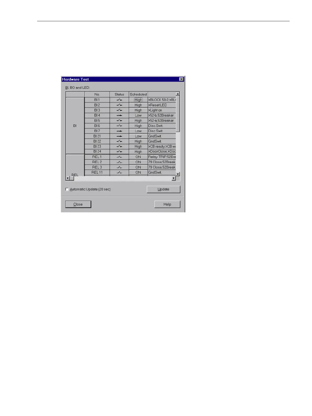
In the column Status the present (physical) state of the hardware component is displayed. Indication is made
by symbols. The physical actual states of the binary inputs and outputs are indicated by an open or closed
switch symbol, the LEDs by a dark or illuminated LED symbol.
The opposite state of each element is displayed in the column Scheduled. The display is made in plain text.
The right-most column indicates the commands or messages that are configured (masked) to the hardware
components.
[ein-ausgabe-testen-110402-wlk, 1, en_US]
Figure 3-24
Test of the binary inputs/outputs — example
Changing the Operating State
To change the status of a hardware component, click on the associated button in the Scheduled column.
Password No. 6 (if activated during configuration) will be requested before the first hardware modification is
allowed. After entry of the correct password a status change will be executed. Further status changes remain
possible while the dialog box is open.
Test of the Output Relays
Each individual output relay can be energized allowing to check the wiring between the output relay of the
7SJ80 and the system, without having to generate the message that is assigned to the relay. As soon as the
first status change for any one of the output relays is initiated, all output relays are separated from the internal
device functions, and can only be operated by the hardware test function. This for example means that a
switching command coming from a protection function or a control command from the operator panel to an
output relay cannot be executed.
Proceed as follows in order to check the output relay:
•
Ensure that the switching of the output relay can be executed without danger (see above under
DANGER!).
•
Each output relay must be tested via the corresponding Scheduled-cell in the dialog box.
•
Finish the testing (see margin title below “Exiting the Test Mode”), so that during further testings no
unwanted switchings are initiated.
Mounting and Commissioning
3.3 Commissioning
SIPROTEC 4, 7SJ80, Manual 339
E50417-G1140-C343-A8, Edition 12.2017

 Loading...


