•
If not, first check whether one of the aforesaid messages 170.2090
25 V2>V1
or 170.2091
25 V2<V1
or 170.2094
25 α2>α1
or 170.2095
25 α2<α1
is available in the spontaneous messages.
The message
25 V2>V1
or
25 V2<V1
indicates that the magnitude adaption is incorrect. Check address
6121 Balancing V1/V2 and recalculate the adaptation factor.
The message
25 α2>α1
or
25 α2<α1
indicates that the phase relation of the busbar voltage does not
match the setting under address CONNECTIONof V2 (see Section 2.20 Synchrocheck). When measuring
via a transformer, address 6122 ANGLE ADJUSTM. must also be checked; this must adapt the vector
group. If these are correct, there is probably a reverse polarity of the voltage transformer terminals for
V1.
•
For the synchrocheck, the program SYNC V1>V2< is set to YES (address 6108)
•
Open the VT mcb of the busbar voltage.
•
Via a binary input (170.0043
>25 Sync requ.
) a measurement request is entered. There is no close
release. If there is, the VT mcb for the busbar voltage is not allocated. Check whether this is the required
state, alternatively check the binary input
>FAIL: BUS VT
(6510).
•
Close the VT mcb of the busbar voltage again.
•
Open the circuit breaker.
•
For the synchrocheck, the program SYNC V1<V2>is set to YES (address 6107) and SYNC V1>V2< is set
to NO (address 6108).
•
Via a binary input (170.0043
>25 Sync requ.
) a measurement request is entered. The synchrocheck
must release closing (message 170.0049
25 CloseRelease
). Otherwise check all voltage connections
and the corresponding parameters again thoroughly as described in Section2.20 Synchrocheck.
•
Open the VT mcb of the feeder voltage.
•
Via a binary input (170.0043
>25 Sync requ.
) a measurement request is entered. No close release is
given.
•
Close the VT mcb of the busbar voltage again.
Addresses 6107 to 6110 must be restored as they were changed for the test. If the allocation of the LEDs or
signal relays was changed for the test, this must also be restored.
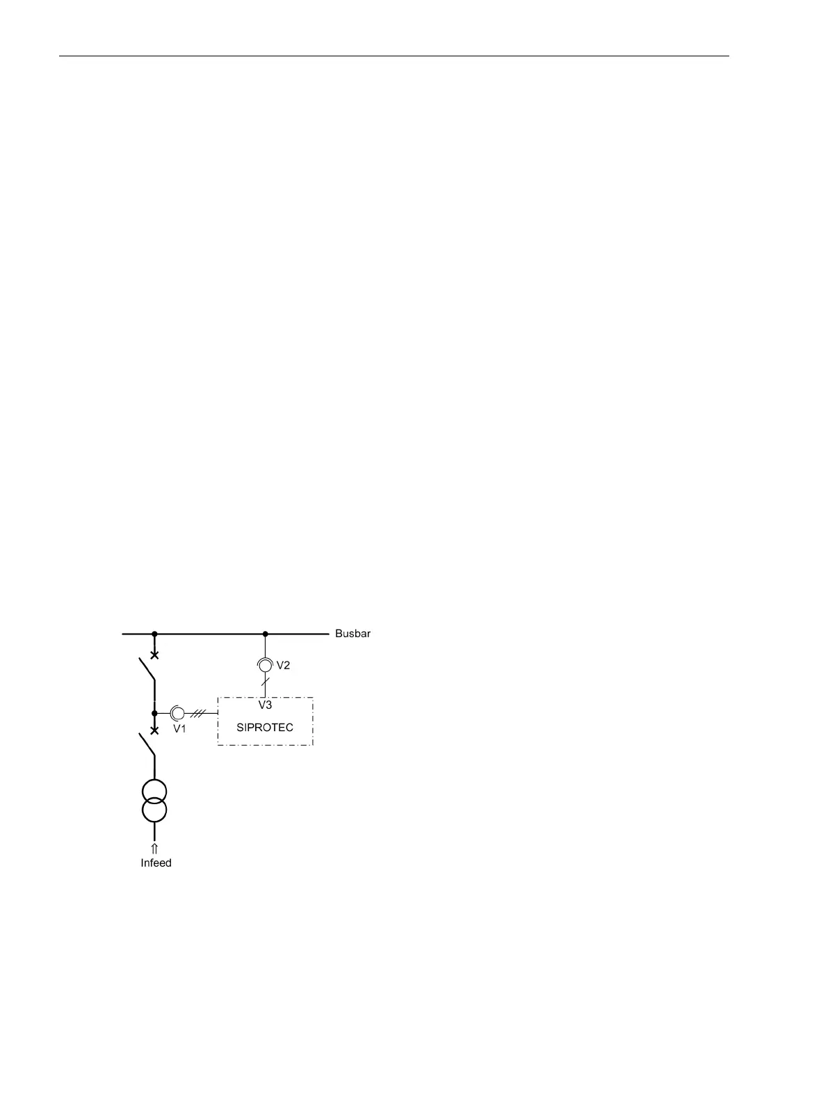
[messspan-synch-kontr-20070716, 1, en_US]
Figure 3-26 Measuring voltages for synchrocheck
Mounting and Commissioning
3.3 Commissioning
346 SIPROTEC 4, 7SJ80, Manual
E50417-G1140-C343-A8, Edition 12.2017

 Loading...


