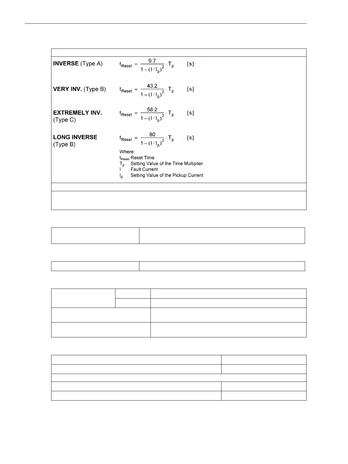
Dropout Time Characteristics with Disk Emulation acc. to IEC
Acc. to IEC 60255-151 or BS 142, Section 3.5.2 (see also Figure 4-1 and Figure 4-2)
The dropout time curves apply to (Ι/Ιp) ≤ 0.90
For zero sequence current, read 3Ι0p instead of Ι
p
and T
3Ι0p
instead of T
p
;
for ground fault, read Ι
Ep
instead of Ι
p
and T
ΙEp
instead of T
p
Dropout Setting
IEC without Disk Emulation
approx. 1.05 · setting value Ι
p
for Ι
p
/Ι
N
≥ 0.3, this corresponds to
approx. 0.95 · pickup value
Reset of the Integration Timer
IEC with Disk Emulation
approx. 0.90 · setting value Ι
p
Tolerances
Pickup/dropout
thresholdsΙ
p
, Ι
Ep
for Ι
Nom
= 1 A
3 % of setting value or 15 mA
for Ι
Nom
= 5 A
3 % of setting value or 75 mA
Trip time for 2 ≤ Ι/Ι
p
≤ 20
5 % of reference (calculated) value + 2 % current tolerance, or
30 ms
Dropout time for Ι/Ιp ≤ 0.90
5 % of reference (calculated) value + 2 % current tolerance, or
30 ms
Influencing Variables for Pickup and Dropout
Auxiliary DC voltage in range 0.8 ≤ V
Aux
/V
AuxNom
≤ 1,15 1 %
Temperature in range –5 °C (23 °F) ≤ Θ
amb
≤ 55 °C (131 °F) 0.5 %/10 K
Frequency in the range of 25 Hz to 70 Hz
Frequency in the range of 0.95 ≤ f/f
Nom
≤ 1.05 (f
Nom
= 50 Hz or 60 Hz) 1 %
Frequency outside range 0.95 ≤ f/f
Nom
≤ 1.05 Increased tolerances
Technical Data
4.3 Inverse-time Overcurrent Protection
366 SIPROTEC 4, 7SJ80, Manual
E50417-G1140-C343-A8, Edition 12.2017

 Loading...


