Function block Explanation Task level
MW_
BEARB
PLC1_
BEARB
PLC_
BEARB
SFS_
BEARB
OR OR - Gate X X X X
REAL_TO_DINT Adaptor X X X X
REAL_TO_INT Conversion X X X X
REAL_TO_UINT Conversion X X X X
RISE_DETECT Edge detector X X X X
RS_FF RS- Flipflop — X X X
RS_FF_MEMO RS- Flipflop with status memory — X X X
SQUARE_ROOT Root Extractor X X X X
SR_FF SR- Flipflop — X X X
SR_FF_MEMO SR- Flipflop with status memory — X X X
ST_AND AND gate with status X X X X
ST_NOT Inverter with status X X X X
ST_OR OR gate with status X X X X
SUB Substraction X X X X
TIMER Timer — X X —
TIMER_SHORT Simple timer — X X —
UINT_TO_REAL Conversion X X X X
UPPER_SETPOINT Upper Limit X — — —
X_OR XOR - Gate X X X X
ZERO_POINT Zero Supression X — — —
Device-specific CFC Blocks
Table 4-1
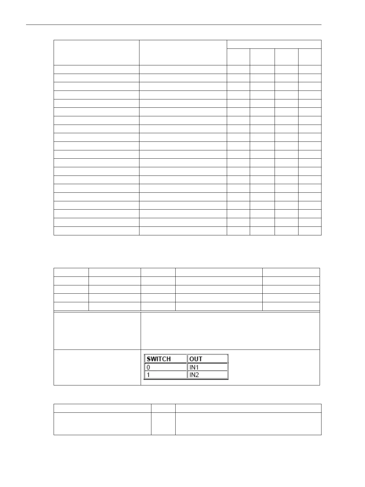
ASWITCH – This block is used to switch between two REAL inputs (RMS values)
Name Type Description Default function
Input SWITCH BOOL Analog value selection FALSE
IN1 REAL Analog value 0.0
IN2 REAL Analog value 0.0
Output OUT REAL Selected analog value
Task levels: Recommendation: Into task levels PLC1_BEARB and PLC_BEARB, because
these levels are directly triggered.
Note: If you use thi block in the task levels MW_BEARB and SFS_BEARB, a
change of the SWITCH signal is only recognized if the signal lasts longer
than the processing cycle of the task level.
Behavior of inputs and outputs:
General Limits
Description
Limit Comment
Maximum number of all CFC charts
considering all task levels
32 If the limit is exceeded, the device rejects the parameter
set with an error message, restores the last valid param-
eter set and restarts using that parameter set.
Technical Data
4.22 User-defined Functions (CFC)
412 SIPROTEC 4, 7SJ80, Manual
E50417-G1140-C343-A8, Edition 12.2017

 Loading...


