X
1
/s = 0.34 Ω/km (0.55 Ω/mile) Positive sequence reactance
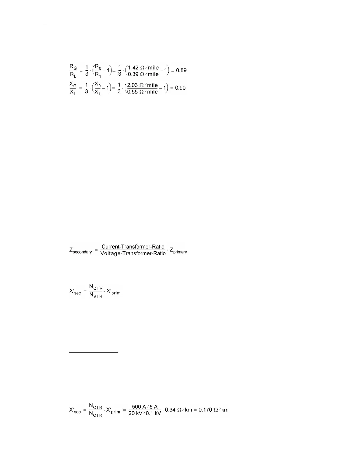
For ground impedance ratios, the following results:
[formfehl-260602-kn, 1, en_US]
Reactance per Unit Length (only for Fault Location)
The setting of the reactance per unit length is only important for the utilization of the line fault location func-
tion. The reactance setting enables the protective relay to indicate the fault location in terms of distance.
The reactance value X' is entered as a reference value x', i.e. in Ω/mile if set to distance unit Miles (address
215, see Section 2.1.3.2 Setting Notes under "Distance Unit") or in Ω/km if set to distance unit km. If, after
having entered the reactance per unit length, the distance unit is changed under address 215, the reactance
per unit length must be reconfigured in accordance with the new distance unit.
The values under address 1106 (km) or 1105 (Miles) apply if only one line section is available and to all faults
that occur outside the defined line sections.
If several line sections are set, the following shall apply:
•
for line section 1, addresses 6004(km) or 6003 (Miles)
•
for line section 2, addresses 6014 (km) or 6013 (Miles),
•
for line section 3, addresses 6024 (km) or 6023 (Miles).
When setting the parameters in DIGSI, the values can also be entered as primary values. In that case the
following conversion to secondary values is not required.
For the conversion of primary values to secondary values the following applies in general:
[zsekundaer-260602-kn, 1, en_US]
Likewise, the following applies to the reactance per unit length of a line:
[xsekundaer-260602-kn, 1, en_US]
with
N
CTR
— Transformation ratio of the current transformer
N
VTR
— Transformation ratio of the voltage transformer
Calculation example:
In the following, the same line as illustrated in the example for ground impedance ratios (above) and addi-
tional data on the voltage transformers will be used:
Current Transformers
500 A/5 A
Voltage Transformers 20 kV/0.1 kV
The secondary reactance per unit length is calculated as follows:
[xsekund-beispiel-260602-kn, 1, en_US]
Functions
2.1 General
SIPROTEC 4, 7SJ80, Manual 51
E50417-G1140-C343-A8, Edition 12.2017

 Loading...


