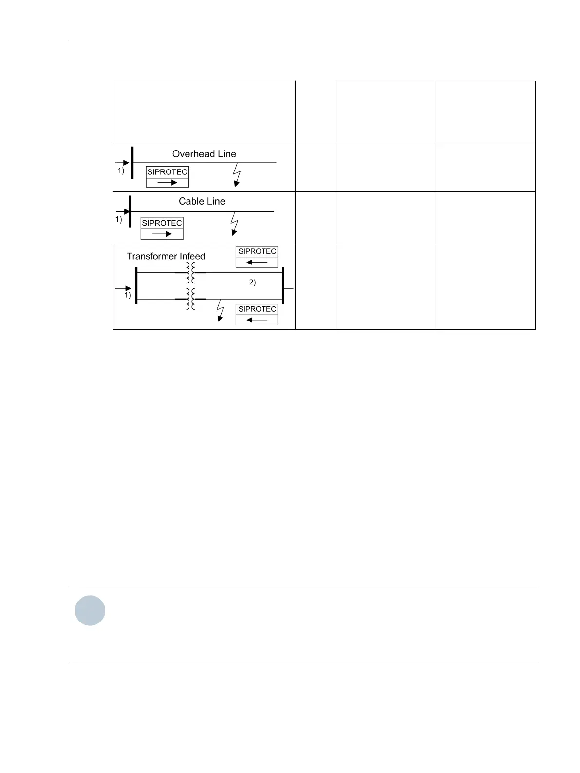
Table 2-7 Setting examples
Application φ
k
typical
Setting
Directional Phase
Element
1519 ROTATION
ANGLE
Setting
Directional Ground
Element
1619 ROTATION
ANGLE
60° Bereich 30°...0°
→ 15°
–60°
30° Bereich 60°...30°
→ 45°
–30°
30° Bereich 60°...30°
→ 45°
–30°
1)
Power flow direction
2)
With the assumption that these are cable lines
Directional Orientation
Directional overcurrent protection normally operates in the direction of the protected object (line, trans-
former, etc.). If the protection device is properly connected in accordance with one of the circuit diagrams in
Appendix C Connection Examples, this is the “forward” direction.
The directional orientation Forward or Reverse can be set separately for each element. Moreover, each
element can also be operated Non-Directional.
•
Address 1526 67-3 Direction
•
Address 1523 67-2 Direction
•
Address 1524 67-1 Direction
•
Address 1525 67-TOC Direct.
•
Address 1626 67N-3 Direction
•
Address 1623 67N-2 Direction
•
Address 1624 67N-1 Direction
•
Address 1625 67N-TOC Direct.
NOTE
If the threshold value of the 67-1 or 67N-1 element is exceeded, the phase-specific directional indications
“forward” or “reverse” are output (indications 2628 to 2636), independent of whether the fault direction is
the same as the configured direction.
These indications are used for directional comparison protection.
Quantity Selection for Direction Determination for the Directional Ground Element
Parameter 1617 67N POLARIZAT.can be set to specify whether direction determination is accomplished
from the zero sequence quantities or ground quantities (with VN and IN) or from the negative sequence
Functions
2.3 Directional Overcurrent Protection 67, 67N
SIPROTEC 4, 7SJ80, Manual 97
E50417-G1140-C343-A8, Edition 12.2017

 Loading...


