Description Of Specific Functions
V800 Series High Performance Closed-Loop Vector Inverter User Manual
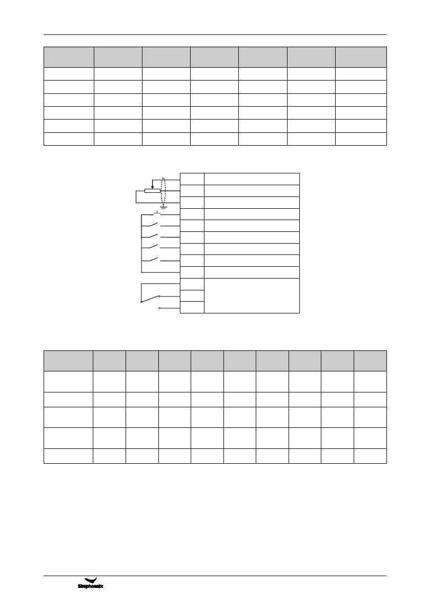
6: Machine tool spindle drive/Al1 setting
AI1
Revolution given: 0~10V
GND
Analog input address
+10V
Reference voltage: 10 VDC, max.
10mA
DI2
Shifting jog
DI3
Switch disengaged: FWD command
DI4
Switch engaged: REV command
DI5
Fault resetting input (RESET)
DI6
Motor switching
CM
Digit input public address
TA
Fault output
TB
TC
1~10KΩ
Associated macro parameters
X _ _ _ : System macro (0~F)
The system macro cannot be modified unless correct modification password [F0.0.02] is set. Refer to the
instructions of F0.0.02 parameter for details. Modification of system macro will automatically lead to
initialization of all functional parameters (Group FF parameters will not be initialized unless FF.0.00 allows for
initialization).
0: Standard operation mode
1: Steady load operation
Applicable to steady load (e.g. fan and pump load). In this mode, the load capacity of the equipment will be
automatically increased by one power grade, and the initialization value of motor parameters will be also
Figure 7-4 Machine tool spindle driving macro AI1 setting wiring diagram