Description Of Specific Functions
V800 Series High Performance Closed-Loop Vector Inverter User Manual
being FWD direction for single polarity setting) and the running command direction.
Frequency
setting source 1
Panel digital setting
Multi-stage frequency
for terminal selection
[F0.1.21]
………
[F0.2.28]
[F0.2.27]
F0.2.25
Channel selection for
frequency source 1
Frequency
setting source 2
Panel digital setting
Multi-stage frequency
for terminal selection
………
[F0.2.31]
[F0.2.30]
F0.2.26
Channel selection for
frequency source 2
Frequency
set value
[F0.1.22]
F0.1.16
Frequency
setting
combination
0: Channel 1 Hz setting
The frequency setting source 1 is independently effective. In this case, the frequency set value is solely
determined by the frequency setting source 1 and is named as the set value 1.
1: Channel 2 Hz setting
The frequency setting source 2 is independently effective. In this case, the frequency set value is solely
determined by the frequency setting source 2 and is named as the set value 2.
2: Select Channel 1 or 2 Hz via input terminal (Function No. 12)
The frequency setting source is selected by the functional input terminal (Function No. 12) and the terminal
function is set with F3.0 group parameters.
3: Selected via control place selection
The selection of frequency setting source is bound with the start-stop command. In this case, the running
command source is bound with the frequency setting source. That is to say, if the running command source 1
is effective, the frequency setting source 1 is also effective; and if the running command source 2 is effective,
the frequency setting source 2 is effective as well.
4: Channel 1 + Channel 2
Frequency set value = set value 1 + set value 2
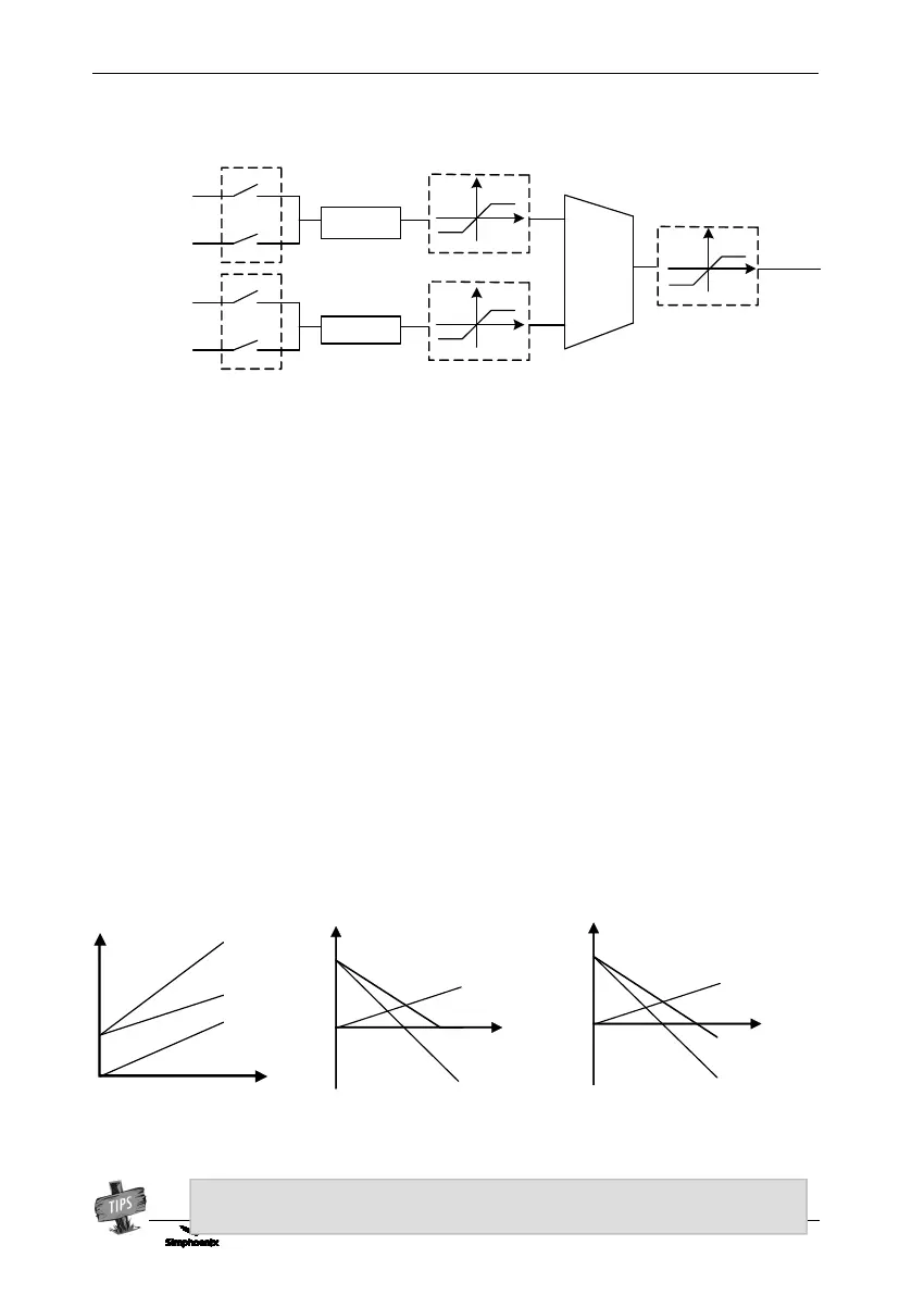
The frequency combination curves under different status are shown as below:
Figure 7-8 Structure sketch of frequency setting channel
The combination result will only be in bipolarity when only two setting sources are set in
bipolarity way. (Figure c)
Figure 7-9-A Frequency combination sketch 1
The combination value can
be reversed (bipolarity)