145
Basic Procedure for DME Wipe Settings
Chapter 6 DME Wipes
• Wave/Ripple: wave and ripple
• Page Turn/Roll: page turn and page roll
• Frame I/O/P in P: frame in/out and picture-in-
picture
• 2D Trans/3D Trans: 2D trans and 3D trans
• Sparkle/Split Slide: sparkle and split slide
• Mosaic/Defocus: mosaic and defocus
• Brick: brick
• User Program: user programmable DME
Selectable DME wipe pattern groups in one-
channel mode: All of the above groups except for
Brick.
Selectable DME wipe pattern groups in two-
channel mode: Slide/Squeeze, Page Turn/Roll,
Frame I/O, PinP, 3D Trans, Brick and User
Program.
Selectable DME wipe pattern groups in three-
channel mode: User Program and Brick.
For details of DME wipe patterns, see “Types of DME
Wipe Pattern” (page 140) and “DME Wipe Pattern
List” (page 312).
The patterns from the selected pattern group appear on
the screen.
3
Press the button to select the desired pattern.
For a key transition, the page turn, page roll and
picture-in-picture cannot be used.
Adjusting DME wipe pattern parameters
Of the DME wipe patterns, the following have parameters
that can be adjusted.
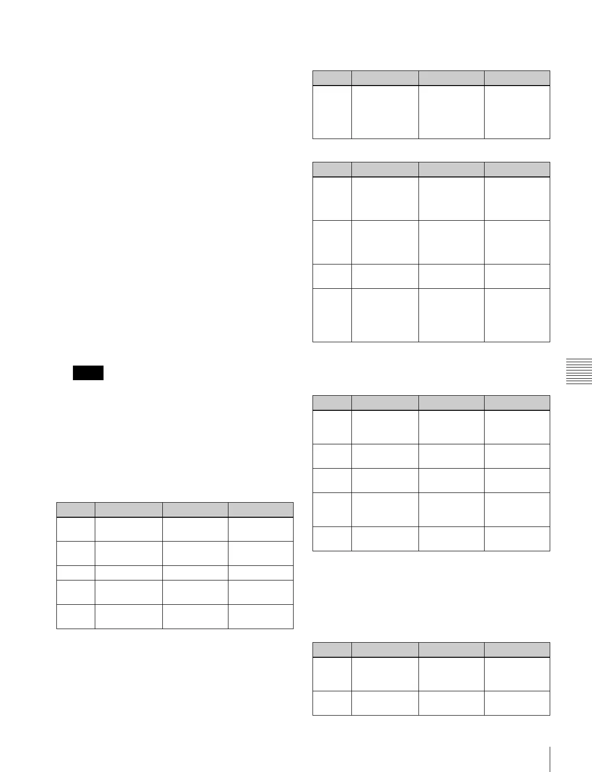
When Brick (for two channels) is selected
(pattern numbers 2801 to 2804, 2811 to 2814)
a) The horizontal center position of the video pasted on Side V. At –100.00
the center is at the left edge of the screen, and at +100.00 the center is at
the right edge of the screen.
b) The vertical center position of the video pasted on Side V. At –100.00 the
center is at the bottom edge of the screen, and at +100.00 the center is at
the top edge of the screen.
When Frame in-out (for two channels) is selected
• Pattern numbers 2851 to 2854
• Pattern numbers 2861 to 2864
When Brick (for three channels) is selected
(pattern number 3601)
a) Shared with knob 3 for parameter group 2
b) The horizontal center position of the video pasted on Side V. At –100.00
the center is at the left edge of the screen, and at +100.00 the center is at
the right edge of the screen.
c) The vertical center position of the video pasted on Side V. At –100.00 the
center is at the bottom edge of the screen, and at +100.00 the center is at
the top edge of the screen.
Notes
Knob Parameter Adjustment Setting values
1 Side V Size X Horizontal
magnification
0.01 to 8.00
2 Side V Size Y Vertical
magnification
0.01 to 8.00
3 Height Height of brick 0.01 to 100.00
4 Center X Horizontal
center position
–100.00 to
+100.00
a)
5 Center Y Vertical center
position
–100.00 to
+100.00
b)
Knob Parameter Adjustment Setting values
5 Delay Timing for
video selected
on a utility bus
to appear on
the screen
–100.00 to
+100.00
Knob Parameter Adjustment Setting values
1 Rot X Rotation about
the Y axis
(horizontal
direction)
–100.00 to
+100.00
2 Rot Y Rotation about
the X axis
(vertical
direction)
–100.00 to
+100.00
3 Rot Z Rotation about
the Z axis
–100.00 to
+100.00
5 Delay Timing for
video selected
on a utility bus
to appear on
the screen
–100.00 to
+100.00
Parameter group [1/2]
Knob Parameter Adjustment Setting values
1 Side V Size X Side V
horizontal
magnification
0.01 to 8.00
2 Side V Size Y Side V vertical
magnification
0.01 to 8.00
3 Height Height of brick 0.01 to
100.00
a)
4 Side V Center
X
Side V
horizontal
center position
–100.00 to
+100.00
b)
5 Side V Center
Y
Side V vertical
center position
–100.00 to
+100.00
c)
Parameter group [2/2]
Knob Parameter Adjustment Setting values
1 Side H Size X Side H
horizontal
magnification
0.01 to 8.00
2 Side H Size Y Side H vertical
magnification
0.01 to 8.00