216
3D Support
Chapter 10 Special Functions
4
Press [FM Link], and set the link to either of the
following.
• To use the frame memory outputs in left and right
combinations, set to On.
• To use the same frame memory output for left and
right, set to Off (no indication).
When [FM Link] is On, frame memory output does not
include ancillary data for the right image.
5
Repeat steps 3 and 4, to set all of the frame memory
outputs for 3D mode.
Functions for which left and right frame memory
outputs are coupled when [FM Link] is On
Pair mode On/Off, clip playback, clip transition
1)
, clip
transition snapshot
Carry out operations other than the above separately for
left and right.
1) When [FM Link] is On, a clip for the right frame memory to be used in the
clip transition cannot be selected in the following menus.
• M/E-1 >Misc >Transition >Clip Transition >Clip menu
• M/E-2 >Misc >Transition >Clip Transition >Clip menu
• P/P >Misc >Transition > Clip Transition > Clip menu
• The selection must be made in the Frame Memory >Clip >Recall menu
Switching the type of DME output signal
(video/key) assigned to a monitor signal
The function for switching the signal type of the monitor
output (one channel) to video or key is assigned to one of
the Prefs buttons of the Menu control block or one of the
buttons of the Utility/Shotbox control block (DME MON
KEY command).
For details of the assignment, see “Settings Button
Assignment (Prefs/Utility Menu)” in Chapter 19 (Volume
2).
To switch the signal type of DME output (video/
key) assigned to a monitor signal
Press the DME MON KEY command assigned button and
turn it on to assign DME key output to a monitor signal.
Then press the button and turn it off to assign DME video
output to a monitor signal. For selection of the DME
channels to be assigned to a monitor signal.
For details, see “Assigning a DME output signal as a
monitor signal” (page 105).
Selecting the signal output from a DME
monitor output connector
1
Display the Engineering Setup >DME >Output
>Monitor Output menu.
2
Press [DME1] or [DME2] to select the DME to
operate on.
3
On the left, select MONI OUT#1 or MONI OUT#2.
4
On the right, select the signal.
You can select any of Ch1 Video, Ch1 Key, Ch2
Video, and Ch2 Key.
5
Press [Set].
This assigns the signal.
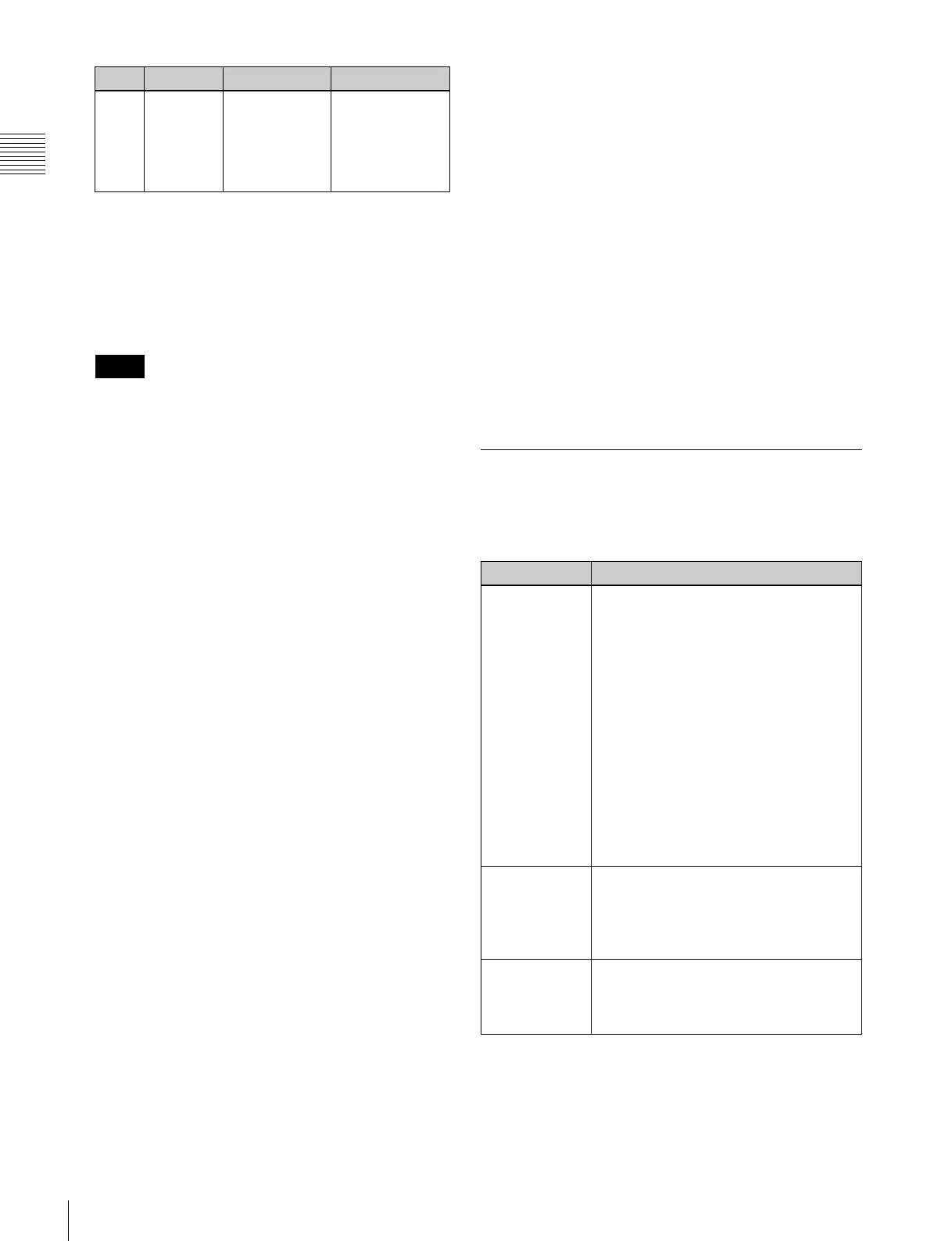
Restrictions in 3D Mode
In 3D mode, the following restrictions apply, because the
switcher and DME hardware is operating in tandem (link
A and link B).
a) In MVS-8000X
b) In MVS-7000X
3 Num Select the
number of
consecutive
numbers from
the selected
link number
1 to 8
Notes
Knob Parameter Adjustment Setting values
Restrictions Details
Functions that
cannot be used
in the switcher
• 73 or more signal inputs (MVS-8000X)
or 41 or more signal inputs (MVS-
7000X)
• 11 or more premium input signals
(MVS-8000X only)
• 25 or more signal outputs
• Monitor buses 2/4/6/8
• M/E-2 bank
a)
• M/E-3 bank
• Key 5 to Key 8
b)
• DME utility buses 1, 2
• Color corrector 2
• Format converter
• Functions of the “Logical M/E Assign” in
the Engineering Setup >Switcher
>Config menu.
Functions that
cannot be used
on the DME
• DME channels 3, 4, 7, 8
• DME monitor output numbers 3 and 4
• Editor ports 3 and 4 when the editor
port operation mode is set to
“Independent”
Other
restrictions
• Auto chroma keying is carried out on
the left image.
• Tallies are generated based on the left
signal in the PGM/PST bank.