515
Interfacing With External Devices (Device Interface Menu)
Chapter 19 Control Panel Setup (Panel)
Carrying out level settings
To set the low level and high level, first set the trigger type
to “Level,” then use the following procedure.
1
In the Panel >Device Interface menu, select the action
to be set, and press [H/L Set].
The H/L Set menu appears.
2
Using any of the following methods, select the
settings.
• Press directly on the list in the status area.
• Press the arrow keys to scroll the reverse video
cursor.
• Turn the knob.
3
To apply the selection made in step 2 when the input
is the GPI high level, press [H Set]. To apply the
selection made in step 2 when the input is low, press
[L Set].
This confirms the setting, which appears in the status
area.
To Set the Level for the Format Converter
1
Set “System Format” for “Action” using the same
operation in Step 5 of “Making Control Panel GPI
Input Settings” (page 513).
The format converter list appears.
2
Select the format converter that you want to set from
the list.
3
In the <FC Input/Output> group, press [H Set] or [L
Set] to set the high level or low level, respectively.
Making Control Panel GPI Output
Settings
1
In the Panel >Device Interface menu, press [GPI
Output].
The GPI Output menu appears.
2
Using any of the following methods, select the
settings.
• Press directly on the list in the status area.
• Press the arrow keys to scroll the reverse video
cursor.
• Turn the knob.
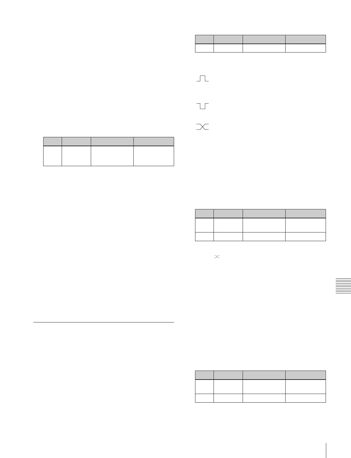
3
In the <Trigger Type> group, select the trigger
polarity.
(Rising Edge): The trigger causes the relay
contacts to be open-circuit or drives the output
high, and holds this state for the specified pulse
width.
(Falling Edge): The trigger causes the relay
contacts to be shorted or drives the output low, and
holds this state for the specified pulse width.
(Any Edge): Each time the trigger occurs, the
relay contacts are alternately closed or opened, or
the output is switched between high and low.
Status: Depending on the status, the relay contacts are
closed or opened, or the output is switched
between high and low.
No Operation: The trigger has no effect on the relay
state or output level.
4
Turning the knobs, select the pulse width and timing to
be set.
a) 1: Field 1, 2: Field 2, 3: Any
When “ ” is selected as the trigger polarity, there is
no Pulse Width setting. When “Status” is selected,
there is no Pulse Width or Timing setting.
5
In the <Source> group, select the action block.
M/E-1 to M/E-4 and P/P: Set an action for the M/E or
PGM/PST bank.
Common: Set an action for error status.
6
Using any of the following methods, select the action
to be set.
• Press directly on the list in the status area.
• Press the arrow keys to scroll the reverse video
cursor.
• Turn the knobs.
a) Action list when the trigger type is other than “Status”
(In M/E-x, the x is the M/E bank number (1 to 4); in DSKx the x is
the DSK number (1 to 8); in Keyx the x is the key number (1 to 8)).
Knob Parameter Adjustment Setting values
1 No Signal format/
screen aspect
ratio selection
1 and upwards
Knob Parameter Adjustment Setting values
1 Port Port selection 1 to 8
Knob Parameter Adjustment Setting values
3Pulse
Width
Pulse width 1 to 60 (fields)
4 Timing Output timing 1 to 3
a)
Knob Parameter Adjustment Setting values
2 Action Action selection 1 and upwards
a)
5 Reg No Register number 1 to 4
b)