542
Settings Relating to Function Links (Link Menu)
Chapter 20 Switcher Setup (Switcher)
3
Press [GPI Link Adjust].
The GPI Link Adjust menu appears.
The status area shows the current setting state of the
selected link, and a list of the selectable video names
or button names, together with the GPI link Enable/
Disable setting for each bus.
4
Using any of the following methods, select what the
setting applies to. For each GPI port there can be up to
eight links.
• Press directly on the list in the status area.
• Press the arrow keys to scroll the reverse video
cursor.
• Turn the knobs.
a) These include main pair numbers 1 to 300, and “Cut” and “Auto
Trans” on each bank.
5
In the <Video/Button> group, press [Select].
The selected video or button name is reflected in the
status area.
To clear a video/button name link
Make the selection to which the setting applies, then in
the <Video/Button> group press [Clear].
6
To select for each bus whether the GPI link setting is
enabled or disabled, use any of the following methods
to select the bus to which the setting applies.
• Press directly on the list in the status area.
• Press the arrow keys to scroll the reverse video
cursor.
• Turn the knob.
7
In the <Bus> group, select any of the following.
Enable: Enable the GPI link setting for the selected
bus.
Disable: Disable the GPI link setting for the selected
bus.
All Enable: Enable the GPI link setting for all buses.
Setting the delay value
1
In the Switcher >Link >GPI Link Adjust menu, turn
the knobs to select the output port for which you want
to set the delay value, and the corresponding delay
value.
2
Press [Delay Set].
This confirms the delay value, which is reflected in the
status area.
Setting the Re-entry Button Operation
Mode
When you select a re-entry button in the cross-point
control block of an M/E block (downstream M/E block),
the output of the upstream M/E block is read in. You can
set the system so that when a GPI link is set for the cross-
point selected on the A
a)
bus of the upstream M/E block
this triggers the GPI output.
In the Switcher >Link >GPI Link menu, set [Re-Entry
Enable] to On or Off.
When this is On, the GPI is executed upstream.
a) When the bus toggle is set to Off, the applicable bus depends on the
position of the fader lever.
• For re-entry, “upstream” applies to a single stage only.
• This setting is common to all GPI output ports.
• GPI output execution on the upstream M/E block is only
possible on buses for which GPI Link is set to “Enable”
in the GPI Link Adjust menu.
• GPI output occurs when you press a re-entry button, the
re-entry button is selected by a macro execution, or you
press the re-entry button on the AUX bus remote panel.
Making a Setting for Linking Two M/
E Banks
You can link any two M/E banks for some operations by
using the Switcher >Link >M/E Link menu.
The operations for which you can link two M/E banks are
as follows.
• Transition execution (auto transition, cut, and fader lever
operation)
• Next transition selection
• Transition type selection
Knob Parameter Adjustment Setting values
1 GPI Port GPI output port
selection
1 to 8
2 Link No Link number
selection
1 to 8
3 Video/
Button No
Selection of
video or button
name to be
linked
1 and upwards
a)
Knob Parameter Adjustment Setting values
4 Bus Bus selection 1 and upwards
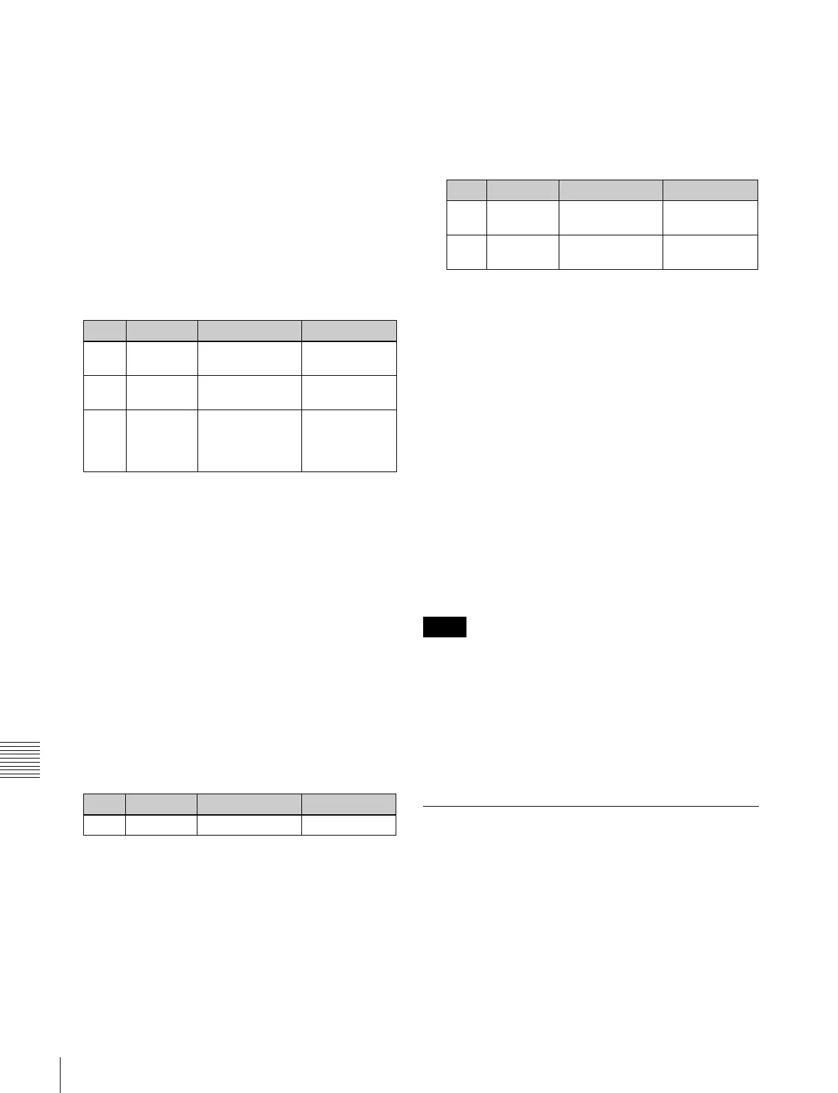
Knob Parameter Adjustment Setting values
1 GPI Port GPI output port
for the setting
1 to 8
5Delay Delay value for
the output port
0 to 300 (fields)
Notes