547
Interfacing With External Devices (Device Interface Menu)
Chapter 20 Switcher Setup (Switcher)
5
In the <Source> group, select the action block.
M/E-1 to M/E-4 and P/P: Set an action for the M/E or
PGM/PST bank.
Common: Set an action for error status.
6
Using any of the following methods, select the action
to be set.
• Press directly on the list appearing in the status area.
• Press the arrow keys to scroll the reverse video
cursor.
• Turn the knobs.
a) Action list when the trigger type is other than “Status”
(In M/E-x, the x is the M/E bank number (1 to 4); in DSKx the x is
the DSK number (1 to 8); in Keyx the x is the key number (1 to 8)).
- When Source is M/E-x: Cut, Auto Trans, Keyx Cut, Keyx Auto
Trans, Keyx SS ? Recall, Effect ? Recall, Effect ? Recall & Run,
KF Run, KF Stop, KF Rewind, No Action
- When Source is P/P: Cut, Auto Trans, DSKx Cut, DSKx Auto
Trans, FTB Cut, FTB Auto Trans, DSKx SS ? Recall, Effect ?
Recall, Effect ? Recall & Run, KF Run, KF Stop, KF Rewind, No
Action
- When Source is Common: No Action
Action list when the trigger type is “Status”
(In M/E-x, the x is the M/E bank number (1 to 4); in DSKx the x is
the DSK number (1 to 8); in Keyx the x is the key number (1 to 8)).
- When Source is M/E-x: Keyx On, No Action
- When Source is P/P: DSKx On, No Action
- When Source is Common: Error Make, Error Break, No Action
b) When knob 2 selection is “Key Snapshot”
c) When knob 2 selection is “Snapshot” or “Effect”
7
Press [Action Set] to confirm the action selection.
The selected setting appears in the status area.
Test firing the trigger
To test fire the trigger, press [Test Fire].
This outputs a trigger from the selected output port. This is
not output when the trigger type is “Status.”
Enabling or Disabling AUX Bus
Control
1
In the Switcher >Device Interface menu, press [Aux
Control].
The Aux Control menu appears.
2
Select the 9-pin port for the setting, from the
<Control> group.
Remote1: Make the settings for the REMOTE1 port.
Remote2: Make the settings for the REMOTE2 port.
Remote3: Make the settings for the REMOTE3 port.
Remote4: Make the settings for the REMOTE4 port.
3
Using any of the following methods, select the AUX
bus.
• Press directly on the list in the status area.
• Press the arrow keys to scroll the reverse video
cursor.
• Turn the knob.
a) 0: EDIT PVW
1 to 48: AUX1 to AUX48
4
Select whether to enable or disable AUX bus control
from the <Control Mode> group.
Enable: enable control of the port selected in step 2.
Disable: disable control of the port selected in step 2.
Manual: make whether control of the port selected in
step 2 is possible or not depend on the setting in
the Misc menu.
5
Repeat steps 2 to 4 as required to make the settings for
other ports.
Setting the Interface Between the
DME and the Switcher
To set the interface between the DME and the switcher,
proceed as follows.
1
In the Switcher >Device Interface menu, press [DME
Type Setting].
The DME Type Setting menu appears.
2
In the <DME1 Type> group to set DME1 or in the
<DME2 Type> group to set DME2, press either of the
following, turning it on.
Dedicated: The DME has an dedicated interface.
SDI: The DME has an SDI interface.
If the system signal format is set to 1080P and the
DME input/output signal format is set to Dual Link
Mode, the SDI interface cannot be selected.
For details of the connection of DME units and the
switcher, see “MVS-8000X-/7000X-C Installation
Manual.”
Knob Parameter Adjustment Setting values
2 Action Action selection 1 and
upwards
a)
5 Reg No Register number 1 to 4
b)
1 to 99
c)
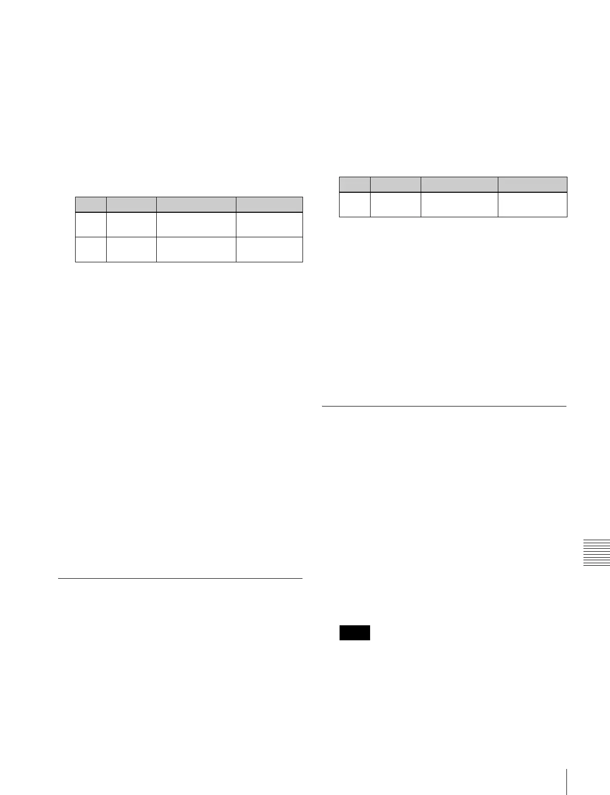
Knob Parameter Adjustment Setting values
1No AUX bus
selection
0 to 48
a)
Notes