44
Names and Functions of Parts of the Control Panel
Chapter 2 Menus and Control Panel
b Operation buttons
The following buttons are used to carry out the
corresponding operations. Function of each button varies
with the operation mode.
When the positioner operation mode is enabled
a) Among these buttons, you can select multiple buttons.
When the three-dimensional transform operation
mode is enabled
The buttons are used for three-dimensional DME
transformations.
For details, see “Three-Dimensional Transformation
Operations” (page 234).
Selected
buttons
Overview of assigned operation
[M/E 1] to
[M/E 4],
[P/P]
• This enables the wipe pattern position
setting (positioner) operation mode in the
device control block.
• You can select multiple buttons
simultaneously.
• When the MKS-9011 1M/E Control Panel is
used, only the [P/P] is enabled. When the
MKS-9012 2M/E Control Panel is used, only
the [M/E-1] and [P/P] are enabled.
For details of [M/E 4] button assignment, see
“Assigning a Button for M/E-4 Selection in the
Setup Menu” (page 344) in Appendix.
[USER] This enables pattern position setting used for
color backgrounds.
[DME 1] to
[DME 8]
• This enables the three-dimensional
transform operation mode in the device
control block.
• Press a button, turning it on, to select a
DME channel.
• You can select multiple buttons
simultaneously.
• The number of valid buttons depends on the
number of DME processor channels
installed.
[DEV] • This enables the VTR/disk recorder/frame
memory operation mode in the device
control block.
• Each button functions as follows.
(From upper left to right in the above figure)
[M/E1] to [M/E3]: DEV1 (device 1) to DEV3
(device 3)
[P/P]: DEV4 (device 4)
[USER]: FM1CLIP (frame memory clip 1)
[FX CTRL]: FM2CLIP (frame memory clip 2)
[DME1] to [DME4]: DEV5 (device 5) to
DEV8 (device 8)
[Unused]: FM LOOP (frame memory loop)
[DME5] to [DME8]: DEV9 (device 9) to
DEV12 (device 12)
• To exit from this mode, press the [DEV]
button again, turning it off.
[RUN
CTRL]
This enables the effect run control mode in
the device control block.
[RSZR
CTRL]
• This enables the resizer control mode in the
device control block.
• In resizer control mode, select the key with
the region selection button [K1RSZ] to
[K8RSZ].
For details on resizer, see page 115.
[FX CTRL] Leave this button off for operation.
Alternatively, for details of operation of this
button, refer to the help information for the
MPES-FX01 Programmable Effector software.
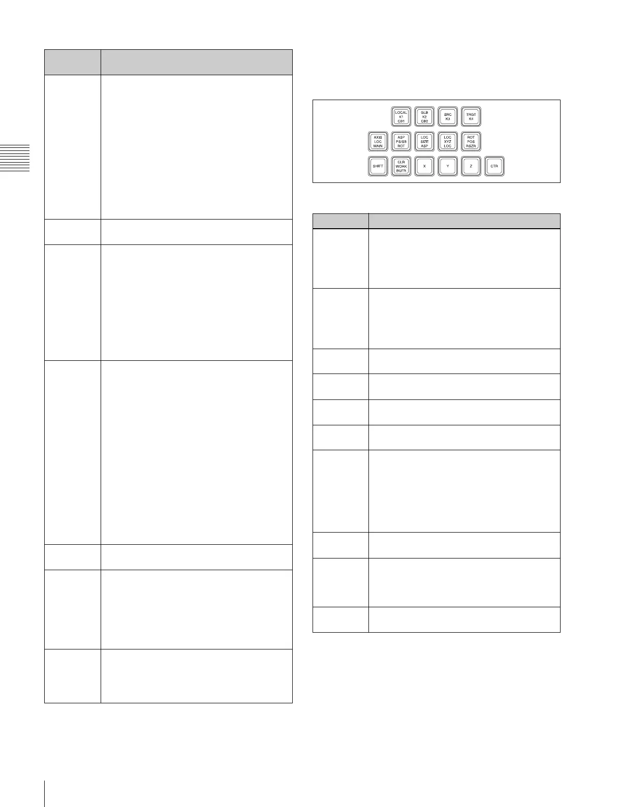
Name Description
K1 CB1
a)
• Press this button to enable wipe pattern
position setting for key 1 (DSK1).
• When the [USER] button is selected,
pattern position setting for color background
1 is enabled.
K2 CB2
a)
• Press this button to enable wipe pattern
position setting for key 2 (DSK2).
• When the [USER] button is selected,
pattern position setting is enabled for color
background 2.
K3
a)
Press this button to enable wipe pattern
position setting for key 3 (DSK3).
K4
a)
Press this button to enable wipe pattern
position setting for key 4 (DSK4).
MAIN
a)
Press this button to enable main wipe pattern
position setting for normal transitions.
SB
a)
Press this button to enable sub wipe pattern
position setting for normal transitions.
POS • Press this button to enable pattern
movement in the x-axis and y-axis
directions with the trackball.
• When the [USER] button is selected, this
enables the trackball to move the pattern in
the x-axis and y-axis directions, and the
Z-ring to adjust the size of the pattern.
X, Y, Z These restrict the axes affected by the
trackball and Z-ring to the x-, y- or z-axis.
CTR
(center)
• When this button is pressed, the pattern
position returns to the center.
• When the [USER] button is selected, the
pattern size also returns to 50.00.
CLR WORK
BUFR
These are not used in positioner operation
mode.