93
Key Setting Operations Using Menus
Chapter 4 Keys
• In the key control block, press the M/E delegation button
[M/E1], then press the key delegation button [KEY1]
twice in rapid succession.
Note that you can access the DSK menus by pressing the
button for the corresponding key in the downstream key
control block twice in rapid succession.
• To select [M/E 4] with the top menu selection buttons, it
is first necessary to assign a button in the Setup menu
(see page 344).
• To select [Key5] to [Key8], and [DSK5] to [DSK8] in
the key control block, a previous assignment in the Setup
menu is required (see page 345).
Key Type Setting
Setting the key type in a menu
1
In the M/E-1 >Key1 menu, select HF1 ‘Type.’
The Type menu appears.
2
In the <Key Type> group, select the key type.
Luminance: luminance key
Linear: linear key
Chroma: chroma key
Color Vector: color vector key
Wipe Pattern: wipe pattern key
Key Wipe Pattern: key wipe pattern key
3
Carry out the following settings as required,
depending on the key type selected in step 2.
To enable clean mode (see page 89) for a luminance
key, linear key or color vector key: Select [Clean
Mode] so that it is set on.
When clean mode is enabled, key fill is added to
the background without cutting out with key
source.
When chroma key is selected: Select [Chroma
Adjust] to access the Chroma Adjust menu (see
page 97), and make the required settings.
When a wipe pattern key is selected: In the M/E-1
>Wipe menu (see page 124), select the pattern and
set any modifiers, then return to the M/E-1 >Key1
menu.
When a key wipe pattern key is selected: In the M/
E-1 >Key1 >
Transition >Wipe Adjust menu (see page 136),
carry out pattern selection and modifier setting,
then return to the M/E-1 >Key1 >Type menu.
For a wipe pattern selected for a wipe pattern key or
key wipe pattern key, the [Edge] and [Direction]
modifier settings are not available.
4
Set the parameters.
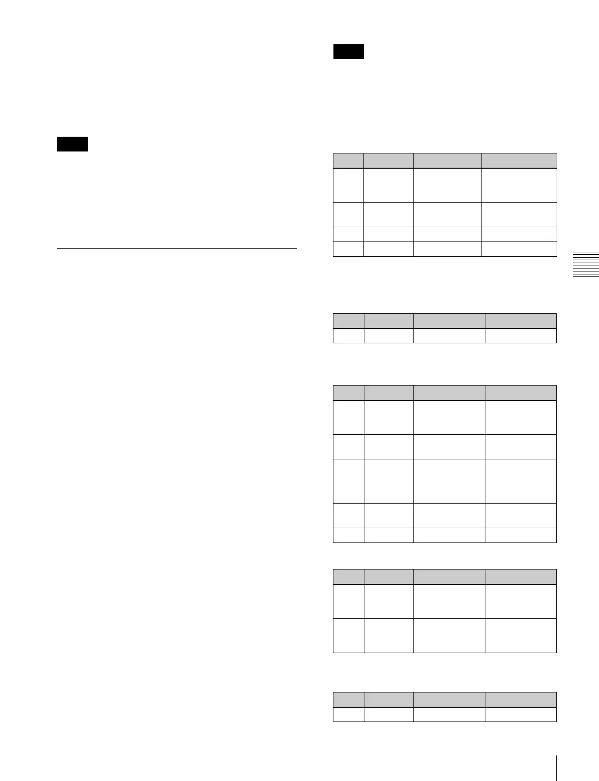
When a luminance key or linear key is selected
a) Setting this value to 1, produces the “through” state in which no filter
is applied. The larger the value, the more strongly the filter applies.
When a chroma key is selected
When a color vector key is selected
When a wipe pattern key or key wipe pattern key is
selected
Notes
Notes
Knob Parameter Adjustment Setting values
1 Clip Reference level
for generating
the key signal
+109.59 to –7.31
2 Gain Key sensitivity –100.00 to
+100.00
3 Density Key density 0.00 to 100.00
4 Filter Filter coefficient 1 to 9
a)
Knob Parameter Adjustment Setting values
3 Density Key density 0.00 to 100.00
Parameter group [1/2]
Knob Parameter Adjustment Setting values
1 Y Clip Reference level
for creating
luminance signal
+109.59 to
–7.31
2 Y Gain Luminance
signal sensitivity
–100.00 to
+100.00
3 C Clip Reference level
for creating
chrominance
signal
100.00 to 0.00
4 C Gain Chrominance
signal sensitivity
–100.00 to
+100.00
5 Density Key density 0.00 to 100.00
Parameter group [2/2]
Knob Parameter Adjustment Setting values
1 Y Filter Luminance
signal filter
coefficient
1 to 9
2 C Filter Chrominance
signal filter
coefficient
1 to 9
Knob Parameter Adjustment Setting values
1 Size Pattern size 0.00 to 100.00