399
Creating and Editing Keyframes
Chapter 13 Keyframe Effects
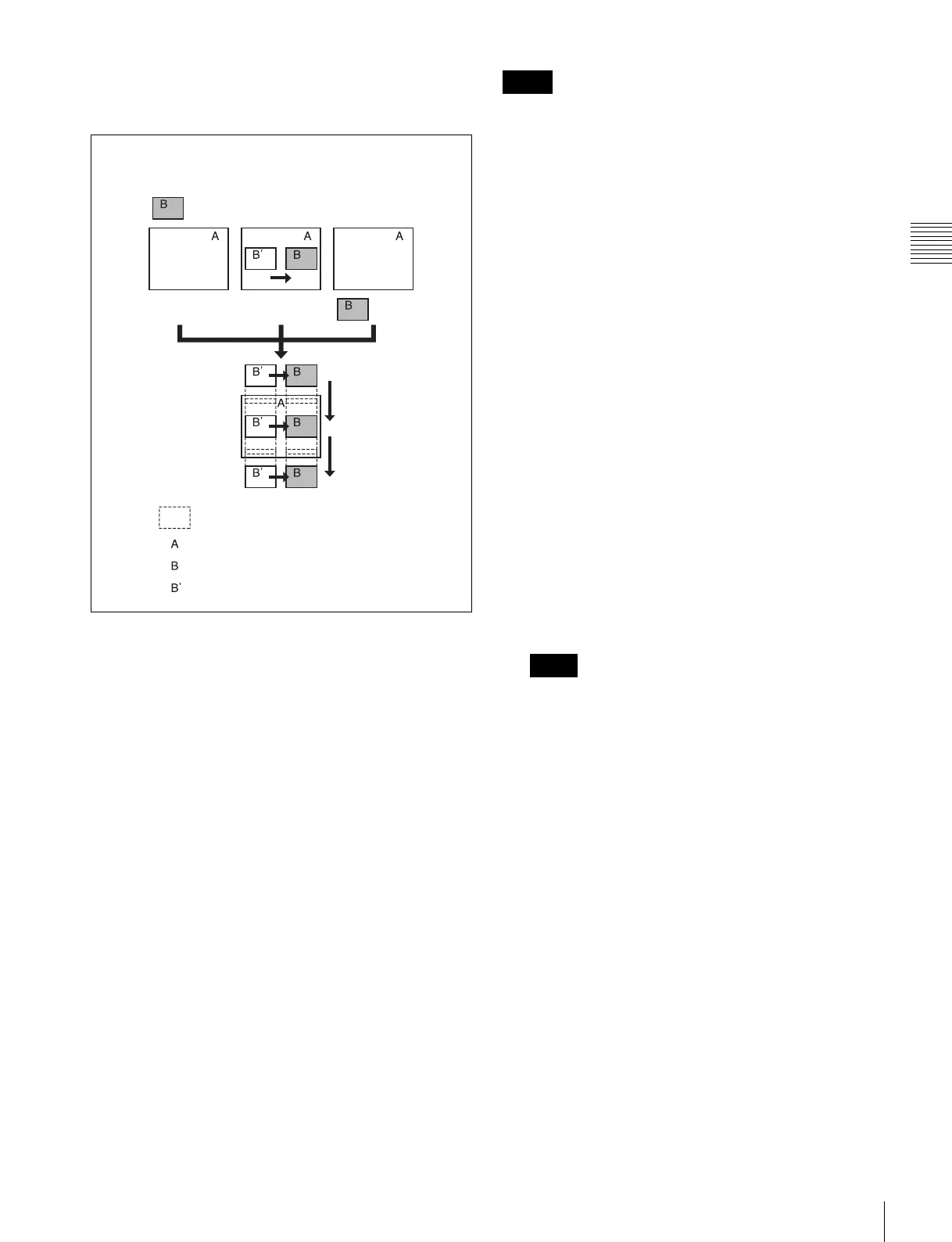
At the first transition completion point, if you move the
image with the positioner, the transition appears as in the
following figure.
Signals forming part of the background for
a DME wipe
For a two-channel mode page turn, page roll, brick, frame
in-out, and so on, the part of the pattern shown in gray is
filled with the signal selected on the DME external video
bus.
For three-channel mode brick, the part of the pattern
shown in dark gray is filled with the DME external video
signal, and the light gray portion with the signal selected as
follows.
For details on the pattern, see “DME Wipe Pattern List”
in Appendix (Volume 1).
For a DME dedicated interface
• When the DME channel used is 3 or 4, the signal
selected on the DME utility 1 bus.
• For channel 7 or 8, the signal selected on the DME utility
2 bus.
For a DME SDI interface
Signal selected on the AUX bus assigned in the
Engineering Setup >Switcher >Device Interface >DME
Type Setting >DME SDI interface menu. (The AUX bus is
determined by which DME channel is being used.)
For the SDI interface on the DME, in some cases the AUX
bus is used in place of the DME external bus (see page
548).
Setting the transition mode
1
In the Key Frame menu, select HF4 ‘DME User
PGM.’
The DME User PGM menu appears.
2
In the <Transition Mode> group, select the transition
mode according to the DME wipe action.
Single: select single transition mode.
Flip/Tumble: select the flip/tumble transition mode.
Dual: select dual transition mode.
P in P: select picture-in-picture mode.
Compress: select compress mode.
Frame I/O: select frame in-out transition mode.
Frame I/O H: select frame in-out transition mode in
the horizontal direction.
Frame I/O V: select frame in-out transition mode in
the vertical direction.
For details of creating an effect for user
programmable DME, see “Creating User
Programmable DME Patterns” in Chapter 6 (Volume
1).
Which DME channel is selected as the reference
region (lit green) in the numeric keypad control block
is reflected in the <Transition Mode> group display.
State before modification
Image created by interpolation
Background B
Background A
Transition start Transition end
First transition
completion
point
Effect execution
Notes
Notes
 Loading...


