Alignment
6-5
b. Move the stage by hand and set it so the vertical edge facing the
rod is placed at the third reference mark from the end of the slide.
There are reference marks scribed on the vertical surface of the
nonmoveable dovetail. They are very fine and can be hard to see.
c. Tighten the setscrew.
8. Set the initial position for cavity focusing mirror M
2
by adjusting the
M
2
micrometer for “7” on the gradation scale (Figure 6-4).
9. Align pump beam steering mirror P
1
.
a. Verify the pump laser is set for minimum current.
b. Open the pump laser and Tsunami shutters.
c. Center the pump beam on P
1
(Figure 6-5) using the vertical and
horizontal adjustments on the routing mirrors.
d. Adjust P
1
vertically and horizontally to center the pump beam on
P
2
.
10. Align pump beam focusing mirror P
2
.
Vertically and horizontally adjust the tilt of P
2
to direct the pump beam
through M
3
and the rod, and center the emerging beam on M
2
(Figure 6-
4 and Figure 6-5).
Centering the beam on the intracavity surfaces of M
2
and M
3
is critical
for proper mode overlap in the rod. If the beam is centered on M
2
but
not on M
3
, walk the pump beam on P
2
, adjusting both P
1
and P
2
, until
proper alignment is achieved.
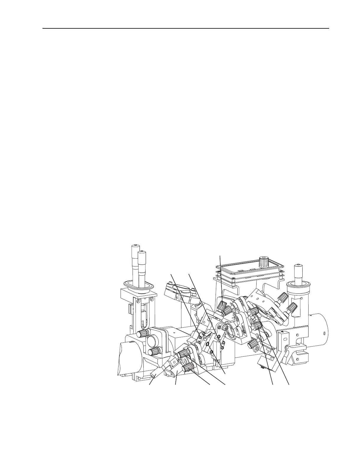
Figure 6-4: Cavity Focus Mirrors
M
2
and M
3
and the Laser Rod
Rod Locking
Screws (2)
Upper Lower
Rod Translation
Control
Rod Face
Horiz. Vert.
M
3
Cavity Focus Mirror
Horiz. Vert.
M
2
Cavity Focus Mirror
Pump Beam
Dump
M
2
Translation
Control