Tsunami Mode-Locked Ti-sapphire Laser
6-6
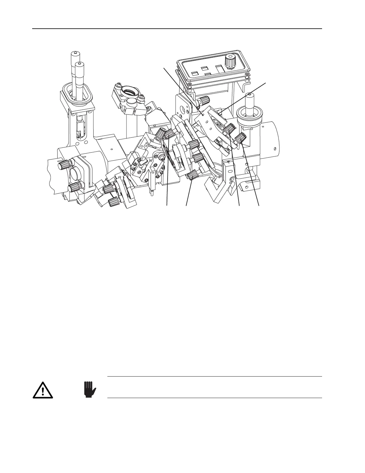
Figure 6-5: Pump Mirrors P
1
and P
2
11. Align cavity focus mirror M
2
.
Adjust M
2
vertically and horizontally to direct the small amount of
pump light reflected from M
2
through the center of M
1
.
12. Adjust the focus of M
2
and M
3
.
Use an IR viewer and white card for the following steps.
a. Place the white card in front of
M
4
.
b. Increase the pump laser to maximum power.
c. Adjust M
3
vertically and horizontally to center the image on M
4
.
There will be one or two reflected images visible on the card: one
from
M
3
and perhaps one from M
1
. If only one image is visible,
adjust
M
1
until two are present. The stationary image is from M
3
.
Note: they need not over-lap at this time.
d. Remove the white card.
e. Temporarily remove the
M
4
mirror to allow the fluorescence to
shine on the output bezel, then tape a white card in the florescence
image on the bezel. An IR viewer may be necessary to see the
image when using the long or
x-long optics set.
Vert. Horiz.
P
1
Pump
Steering Mirror
Horiz. Vert.
P
2
Pump
Focusing Mirror
P
2
Setscrew
On bottom,
opposite this hole.
P
2
Translation
Screw
Caution!
Perform Steps e, f, h, i, and j only if you changed the focus of P
2
, M
2
or
M
3
during this alignment session, otherwise skip to the next section.