187
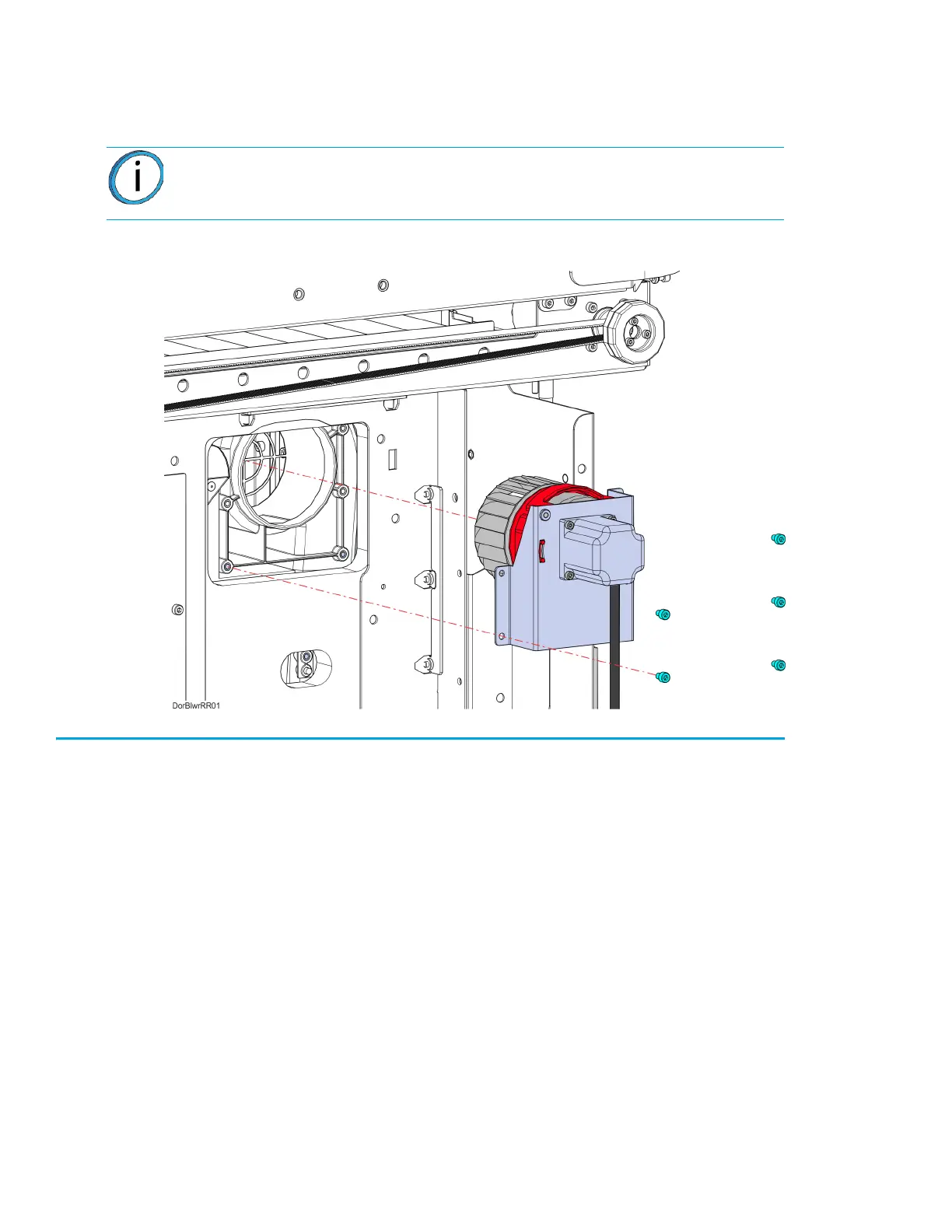
6. Using a 3 mm hex wrench, remove the mounting screws (5) that secure the blower assembly to
the oven frame, see Figure 7-29.
7. Remove the blower assembly from the printer. See Figure 7-29.
Figure 7-29: Right Side Blower Assembly Mounting Screw Locations
Installing the Oven Blower Assembly
1. Using a 3 mm hex wrench, reinstall the blower assembly mounting screws (5). See Figure 7-29.
2. Make sure the blower motor cable is routed properly and secured with tie wraps.
3. Reconnect the fan blower motor cable connector to the I/O board (J39 - right blower, J37 - left
blower).
4. Right-side oven blower only: Using a 2.5 mm hex wrench, reinstall the mounting screws (2)
that secure the side bezel to the printer.
5. Reinstall the side panels. See “Installing the Side Panels” on page 172.
6. Reinstall the rear panel. See “Installing the Rear Panel” on page 170.
Note: Right side oven blower shown only. The left side blower procedure is
identical to the right.