64 Sun Server X4-2 Service Manual • May 2014
Related Information
■ “Servicing CRUs That Require Server Power-Off” on page 61
■ “Servicing FRUs” on page 99
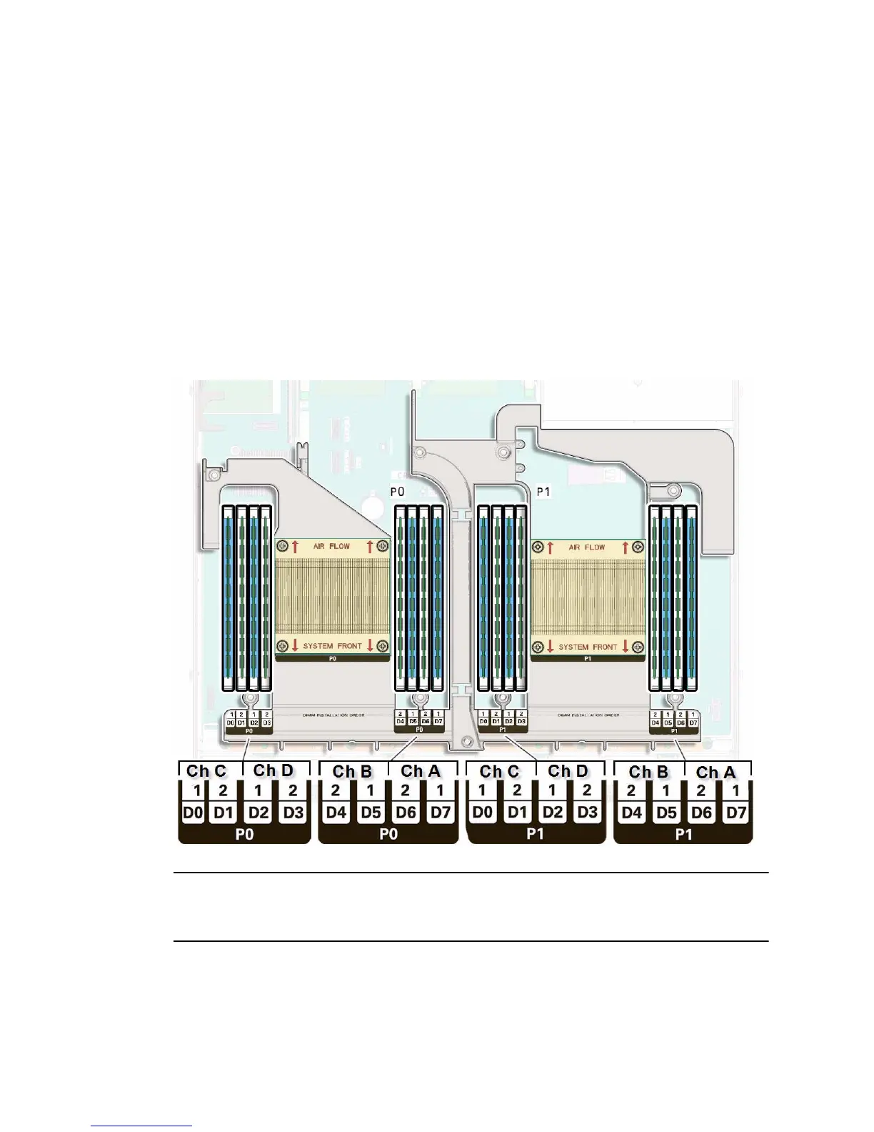
DIMM and Processor Physical Layout
The physical layout of the DIMMs and processor(s) is shown in the following figure.
When viewing the server from the front, processor 0 (P0) is on the left.
FIGURE: DIMM and Processor Physical Layout
Note – In single-processor systems, the DIMM sockets associated with the processor
1 (P1) socket are nonfunctional and should not be populated with DIMMs or DIMM
filler panels.