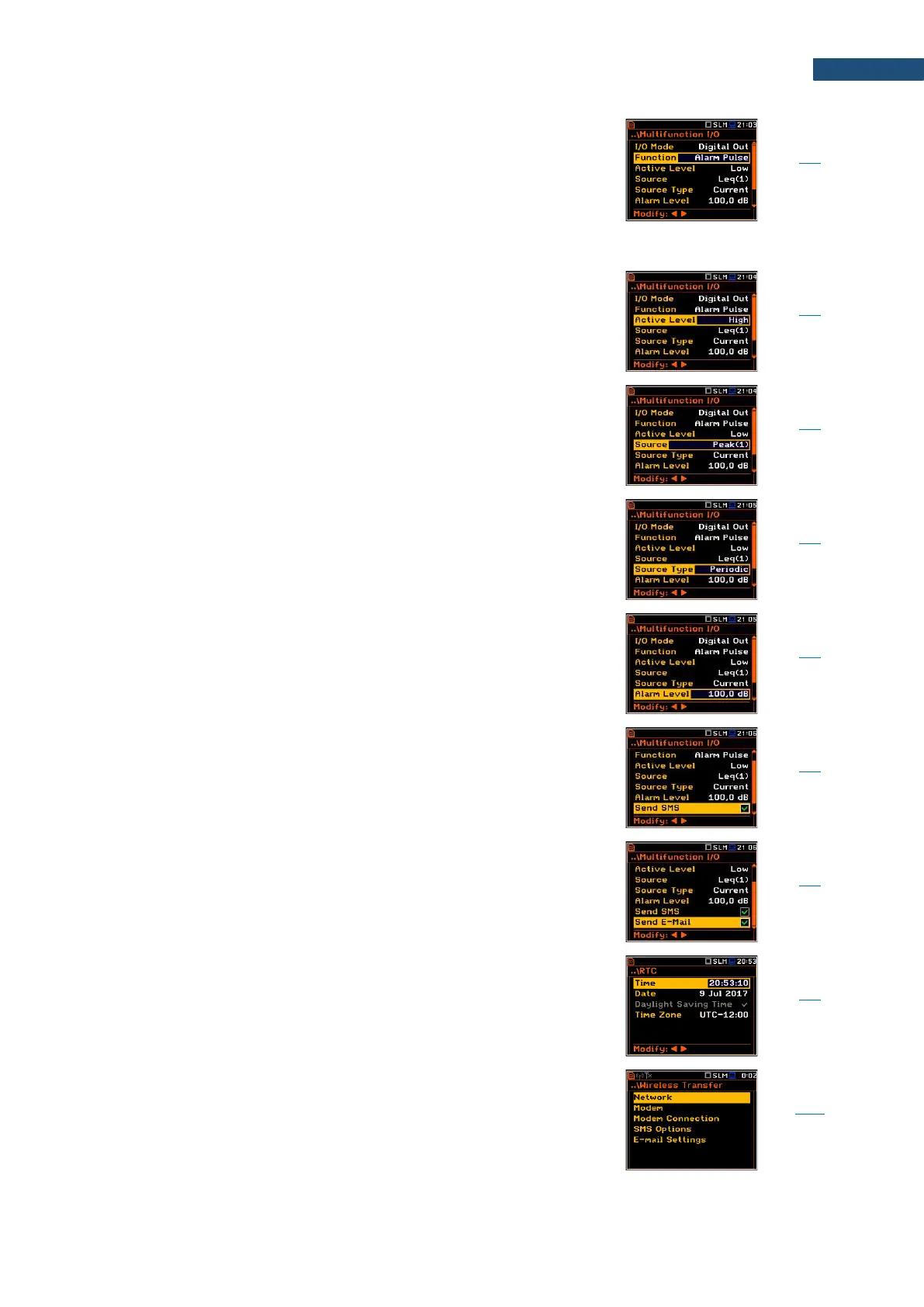
Functionality of the Digital Out I/O mode when digital
signal is used as a source of alarm signal in case of
certain circumstances occurred during measurements
(i.e. the level of the input signal was higher than a user
selected trigger alarm setting). A set of additional
parameters are used for this functionality of the
Digital Out I/O mode: Active Level, Source,
Source Type, Alarm Level, Send SMS and Send E-mail.
Parameter, when Alarm Pulse is selected as a function
of the Digital Out I/O mode, defining the level of the
signal, treated as an alarm: Low (0 V) or High (3 V).
Parameter, when Alarm Pulse is selected as a function
of the Digital Out I/O mode, defining the measured result,
the level of which should be checked for alarm
generation. The measurement results from the first
profile: Peak(1), Spl(1), Max(1) or Leq(1) can be used.
Parameter, when Alarm Pulse is selected as a function
of the Digital Out I/O mode, defining the type of Source:
Current (measured with 1 second step) or Periodic
(measured with Integration Period step).
Parameter, when Alarm Pulse is selected as a function
of the Digital Out I/O mode, defining the threshold level
of the result to be monitored during the measurement. If
the result is greater than the alarm level, the instrument
will generate the alarm signal in the selected logic.
Activation of alarm SMS sending via Wireless Transfer
when Alarm Pulse is selected as a function of the
Digital Out I/O mode.
Activation of alarm e-mail sending via Wireless Transfer
when Alarm Pulse is selected as a function of the
Digital Out I/O mode.
Screen that enables programming the instrument's real-
time clock. This clock is displayed in the upper right
corner of the display.
Screen that enables configuring data transfer control via
external modem supporting cellular connection through
additional screens: Network, Modem, Modem
Connection, SMS Options and E-mail Settings.
 Loading...


