1
097-55501-01 Issue 6 – June 2003 107
2
5
3
Operational Verification & Configuration
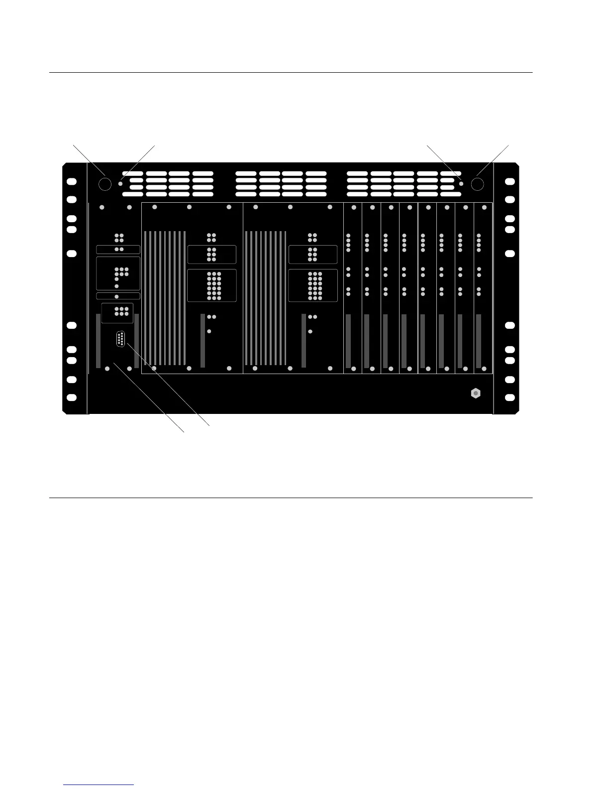
Figure 4-7. –48 Volt Fuses
4.4.2 Confirmation of Master or Remote Shelf Setting
To confirm that the shelf rotary switch has been set properly (see Table ),
power the shelf and insert a clock card into either the CLK1 or CLK2 slot.
The clock card performs a self-test, then enters Warmup mode (the Warmup
LED illuminates). When the card completes Warmup it will transition to
Freerun mode (the Freerun LED illuminates). Following this transition,
check the “Remote” LED per Table . As described, the “Remote” LED will
only illuminate if the shelf has been configured for remote operation. See
Figure for the location of the “Remote” LED. On the clock card front panel,
its location is in the Input section, at the intersection of the row labeled
“DS1 4” and the column labeled “A”. Proper configuration can also be
verified by using the MAINCLK TL1 keyword (see TimeHub 5500 TL1
Reference Manual for details.)
–48 Volt
Fuse B
Fail Lamp
–48 Volt
Fuse B
Management
Card
Local Communication
Port Connector
–48 Volt
Fuse A
Fail Lamp
–48 Volt
Fuse A

 Loading...

