1
097-55501-01 Issue 6 – June 2003 81
2
5
3
Installation
e. If there are more expansion shelves to be connected, repeat
steps a and b.
f. If this is the last expansion shelf in the sequence, connect the
terminating connector to the available link 1 (labeled "Expansion
Link 1 OUT") and link 2 (labeled "Expansion Link 2 OUT") loca-
tions on this shelf. Note that due to the gender differences of
these locations in one case only the termination connector (p/n
090-55505-01) will be needed, in the other case the termination
connector (p/n 090-55505-01) with gender changer (p/n 128-
55505-01) will be needed. It is important to connect the termi-
nation since it provides proper impedance completion which
minimizes reflections that could otherwise affect inter-shelf sig-
nal fidelity. Refer to Figure 3-4.
3.6 Connector Module Installation
3.6.1 Input/Alarm Connector Module (Master and
Remote Shelf Only)
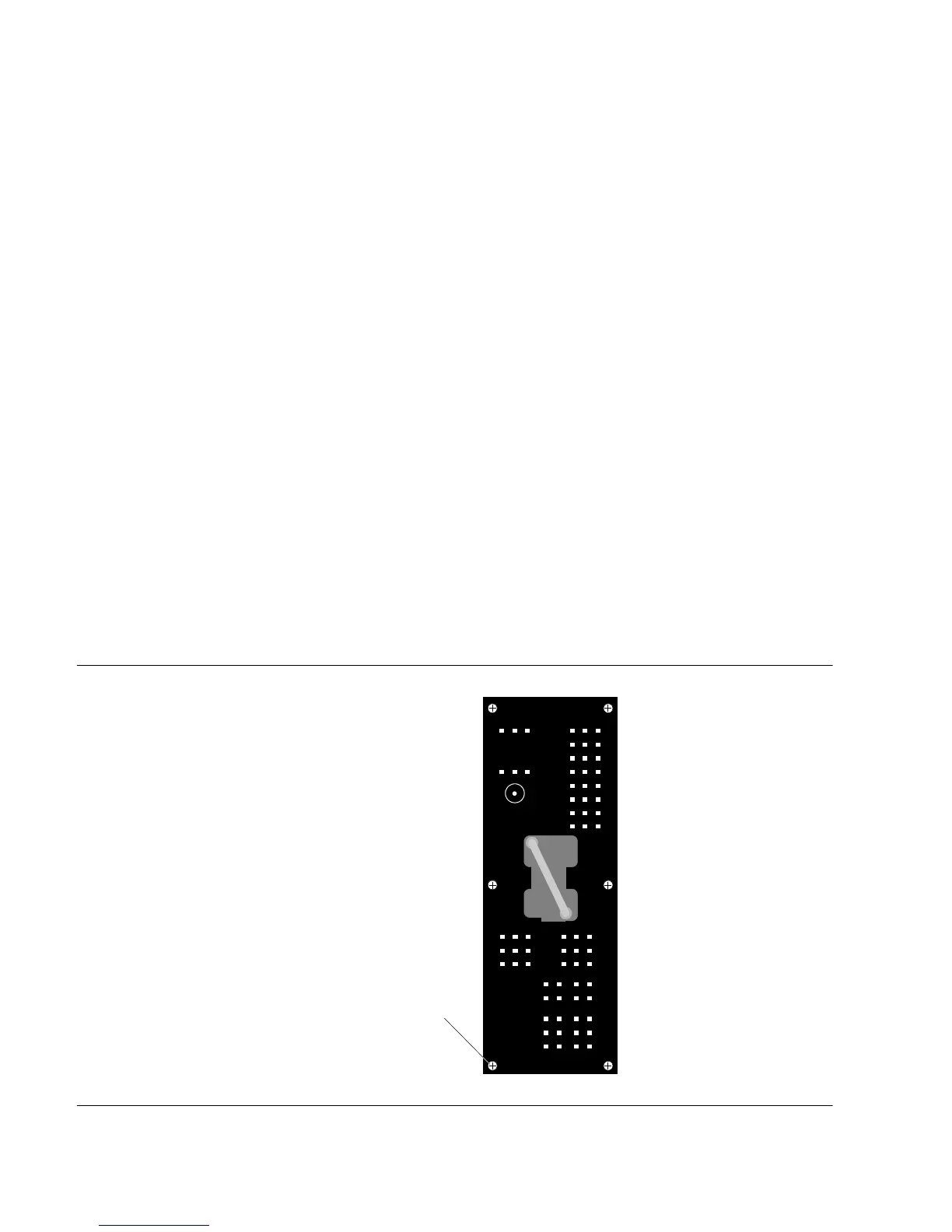
The Input/Alarm Connector module (part number 090-55561-01) is shown
in Figure 3-5. To install the module, use the captive screws to attach the
module to the rear of the shelf, at the right side (Figure 3-6).
Figure 3-5. Input/Alarm Connector Module
Captive Screw (6)

 Loading...

