1
097-55501-01 Issue 6 – June 2003 83
2
5
3
Installation
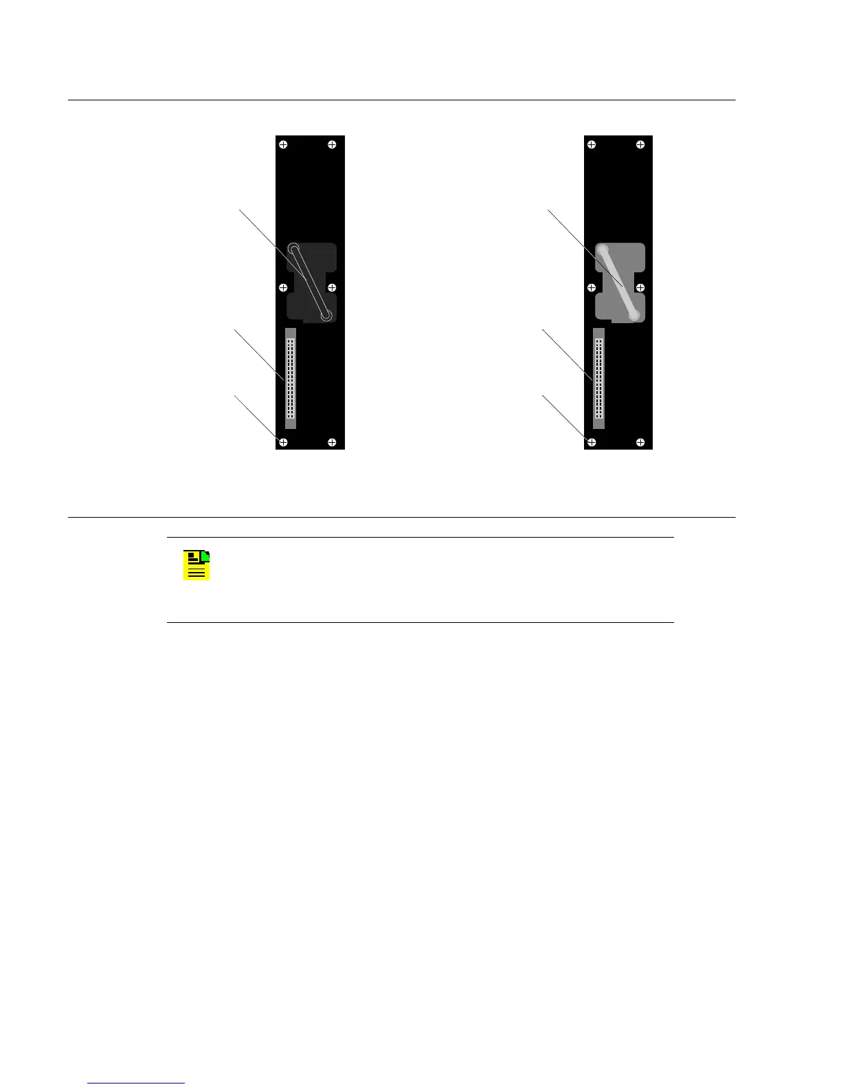
Figure 3-7. Master and Remote Shelf Output Connector Modules
To install the connector modules, use the captive screws to attach the
output connector modules to the shelf (Figure 3-6). Up to seven output
connector modules can be installed.
To better understand how location of connector modules relates to output
driver cards (inserted in next chapter), see “Relationship Between Output
Driver Cards and Expansion Output Connector Modules” in Chapter 1 of
this guide. Although that topic is about expansion shelves, it is applicable to
Master and Remote shelves.
3.6.3 Output Connector Module (Expansion Shelf Only)
Install the appropriate output connector module (Figure 3-8) type.
• For DS1 outputs use connector module p/n 090-55591-02, which
is part of the DS1 Output Module Kit (990-55591-02)
N
OTE
: Output connector module types can be distinguished by
the handle on the module. Each DS1 Output Connector module
is labeled “DS1” and has a black handle; each CC Output
Connector module is labeled “CC” and has a blue handle.
Captive Screw (6)
Output Connector
Blue Handle
CC
Captive Screw (6)
Output Connector
Black Handle
DS1
A. DS1 Output Connector Module B. CC Output Connector Module

 Loading...

