134 097-55501-01 Issue 6 – June 2003
1
TimeHub 5500 System Guide
4.7.3 GPS Input
The GPS connector is reserved for future use.
4.7.4 Local Communication Port
If not using the Local connector on the rear of the shelf to provide an RS-232
link for TL1 command access to the TimeHub 5500, connect to the data
terminal equipment (DTE) equivalent communication port 1 at the nine-pin
connector labeled Local on the management card. See Figure 4-7 for the
location of the connector and Table 4-4 for the connector pinouts.
4.8 Cover Installation
Fit the plastic cover over the rear of the shelf and attach at the upper right
and left corners of the shelf using the captive screws on the cover.
N
OTE
: The Local communincation port on the management
card provides the same function as the Local communication
port on the rear of the shelf.
N
OTE
: Cable connections cannot be made to both of the Local
ports simultaneously; only one port can be used at a time.
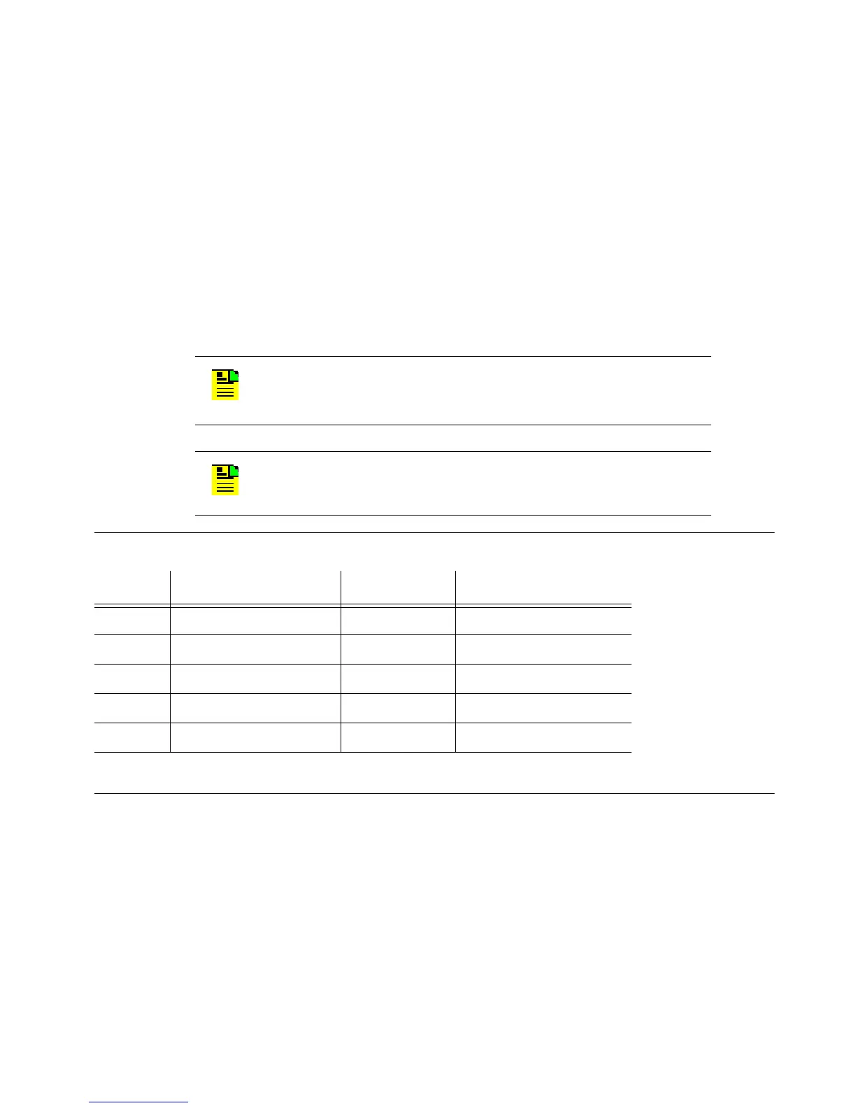
Table 4-4. Local Pinouts
Pin Signal Abbreviation Direction
2 Transmit data TXD From TimeHub 5500
3 Receive data RXD To TimeHub 5500
5 Signal ground GND –
7 Clear to send CTS To TimeHub 5500
8 Request to send RTS From TimeHub 5500
Note: Pins not listed are reserved for future use.

 Loading...

