84 097-55501-01 Issue 6 – June 2003
1
TimeHub 5500 System Guide
• For CC outputs use connector module p/n 090-55593-02, which is
part of the CC Output Module Kit (990-55591-02)
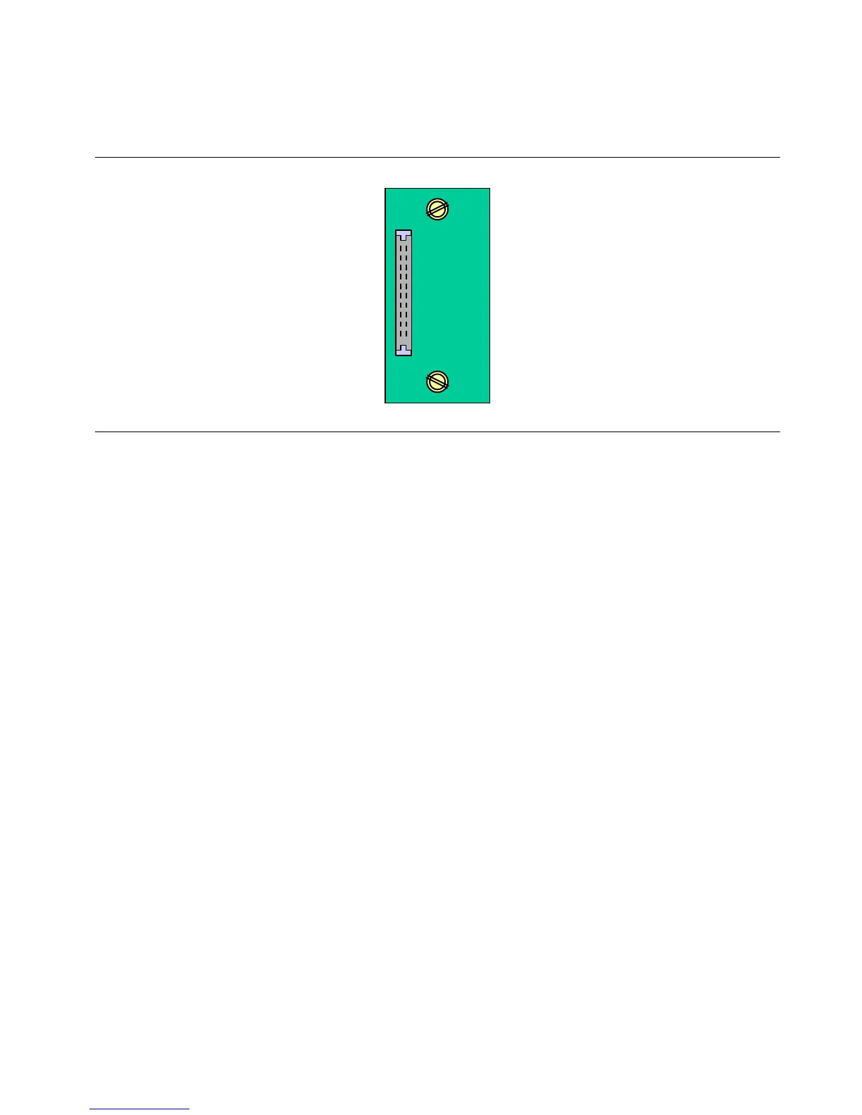
Figure 3-8. Expansion Shelf Output Connector Module
To better understand how location of connector modules relates to output
driver cards (inserted in next chapter), see “Relationship Between Output
Driver Cards and Expansion Output Connector Modules” in Chapter 1 of
this guide.
To install the connector modules, remove them from the captive screws and
align them to the opening in the back on the expansion shelf. The vertical
connector should be facing to the left and the small connector should be on
the bottom facing towards the mate connector on the shelf. Tighten the
screws by hand. Use a small screwdriver if preferred; however, do not
overtighten the screws.
3.7 Blank Panels
3.7.1 Input/Clock Blank Panels (Master and Remote
Shelf Only)
If a TimeHub system is configured with only one input/clock card, install
the blank panel for input/clock card (090-55598-01) in the empty slot space
reserved for the redundant card.
3.7.2 Output Driver Blank Panels (All Shelves)
Install blank panels for output driver cards in the empty slots where output
driver cards are not installed.

 Loading...

