EasyManuals Logo

Symmetricom TimeHub 5500 System Manual

Symmetricom TimeHub 5500
208 pages
To Next Page IconTo Next Page
To Previous Page IconTo Previous Page
Page #97 background imageLoading...
Page #97 background image
1
097-55501-01 Issue 6 – June 2003 97
2
5
3
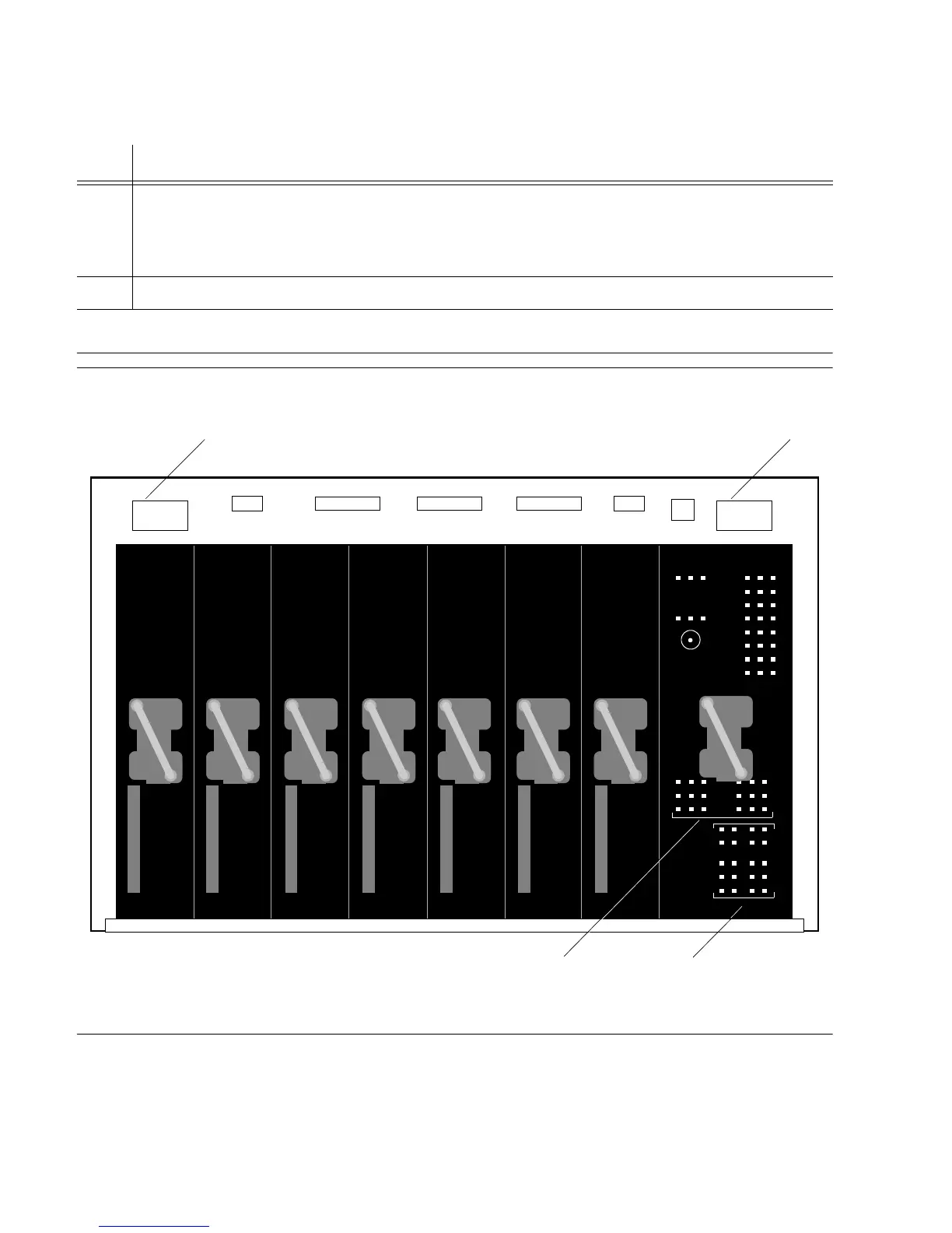
Operational Verification & Configuration
Figure 4-1. Shelf Rear Connectors
8 Use the multimeter to measure the voltage between the
48V B and Return terminal sets
on the TB1 terminal block on the shelf.
The multimeter indicates –42 V dc to –56 V dc.
9 Install both 3AG 10 A fuses (fuse A and fuse B) in the front of the shelf. Refer to Figure 4-1.
End of Procedure
Procedure 4-1. Power Test (Cont’d)
Step Action
Rack AlarmsOffice Alarms
Battery A &
Frame Ground
Battery B &
Frame Ground

Table of Contents

Other manuals for Symmetricom TimeHub 5500

Questions and Answers:

Question and Answer IconNeed help?

Do you have a question about the Symmetricom TimeHub 5500 and is the answer not in the manual?

Symmetricom TimeHub 5500 Specifications

General IconGeneral
BrandSymmetricom
ModelTimeHub 5500
CategoryData Loggers
LanguageEnglish

Related product manuals