1
097-55501-01 Issue 6 – June 2003 89
2
5
3
Installation
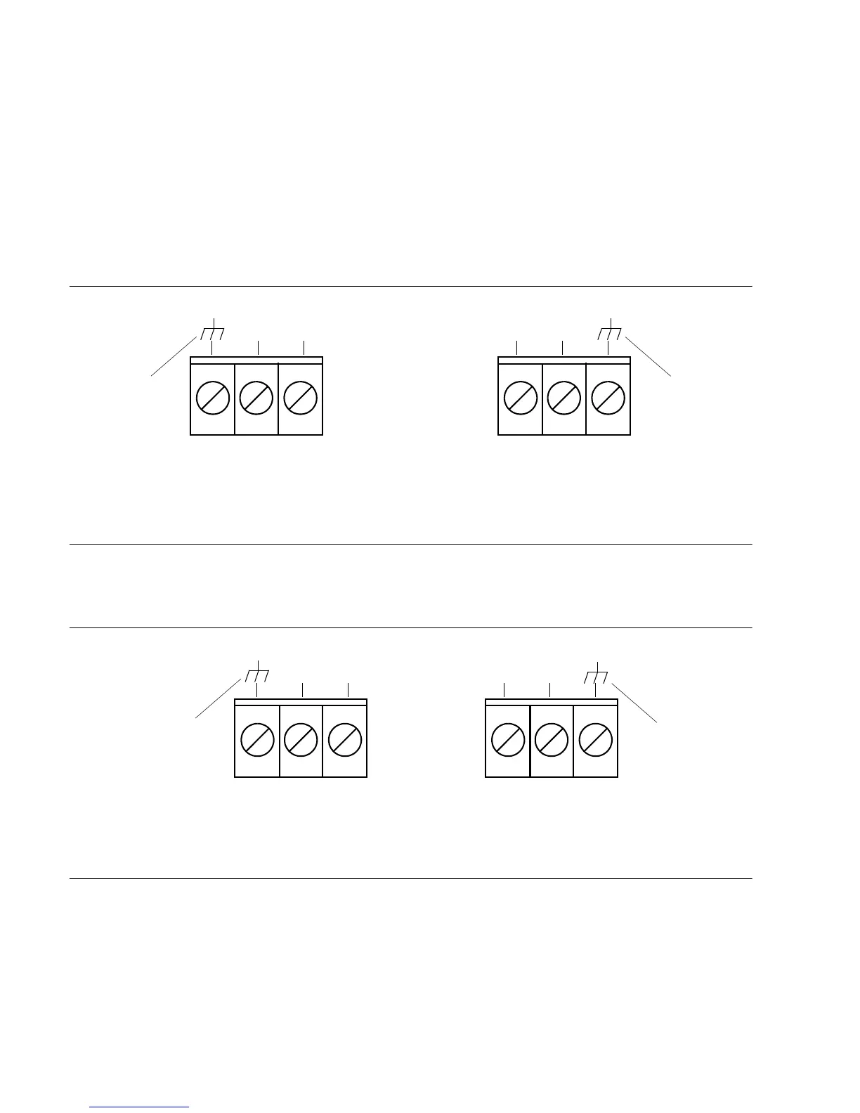
3.8.3.1 Frame Ground
Frame ground connections are made on power terminal blocks TB1 and
TB2. Refer to Figure 3-11 for the location of the terminals, and refer to
Figure 3-12 for the terminal connections.
The terminal connections are labeled. For convenience, the connection order
is shown as well. For a master shelf (090-55501-01), the connections are as
shown in Figure 3-12.
Figure 3-12. Battery Connections (Master Shelf)
For an expansion shelf (090-55502-01), the connections are as shown in
Figure 3-13.
Figure 3-13. Battery Connections (Expansion Shelf)
Ensure the frame ground wires are long enough to go from the rear of the
shelf to the frame ground connection. Use one 16 AWG green insulated wire
to connect the ground terminal of power terminal block TB1 to the frame
ground, and use another 16 AWG green insulated wire to connect the
ground terminal of TB2 to frame ground.
A. TB1 Connections
(Office Battery A)
B. TB2 Connections
(Office Battery B)
TB2TB1
Return
–48V Return –48V
(Ground)(Ground)
A. TB1 Connections
(Office Battery A)
B. TB2 Connections
(Office Battery B)
TB2TB1
Return
–48V
Return–48V
(Ground)
(Ground)

 Loading...

