98 097-55501-01 Issue 6 – June 2003
1
TimeHub 5500 System Guide
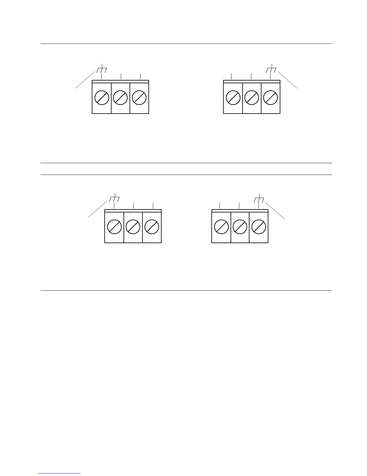
Figure 4-2. Battery Connections (Master Shelf)
Figure 4-3. Battery Connections (Expansion Shelf)
4.3 Input Test
Prior to performing the input test, ensure that the following has been done:
• Connect each available DS1 reference to input connector DS1
input wirewrap pins. Terminated DS1s connect to any of the four
labeled “DS1 TERM IN”; bridged DS1s connect to any of the four
labeled “DS1 BRDG IN”.
• If you have a 5 MHz or 10 MHz PRS input reference, connect it to
the BNC labeled “5/10 MHz IN”
Input signal level requirements for the PRS inputs, DS1 terminated inputs,
and DS1 bridged inputs are covered in Chapter 6.
A. TB1 Connections
(Office Battery A)
B. TB2 Connections
(Office Battery B)
TB2TB1
Return
–48V Return –48V
(Ground)(Ground)
A. TB1 Connections
(Office Battery A)
B. TB2 Connections
(Office Battery B)
TB2TB1
Return –48V
Return–48V
(Ground)
(Ground)

 Loading...

