184 097-55501-01 Issue 6 – June 2003
1
TimeHub 5500 System Guide
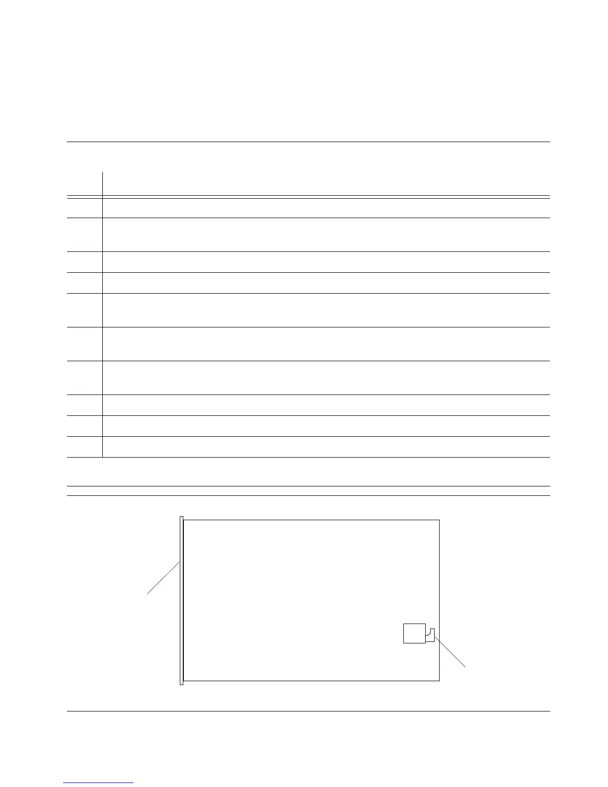
5.3.2 Output Driver Card
To replace the fuse on the output driver card, follow the steps in
Procedure 5-6, and refer to Figures 5-2 and 5-6.
Figure 5-6. Output Driver Card and Management Card Fuse F1
Procedure 5-6. Output Driver Card Fuse Replacement
Step Action
1 Put on a properly grounded ESD wrist strap.
2 Using a #2 Phillips-head or Pozidrive screwdriver, loosen the captive screws at the top and
bottom of the card front panel.
3 Remove the card from the shelf.
4 Using a GMT fuse puller, remove the fuse from the fuseholder labeled F1.
5 Replace the fuse with a 1 amp GMT fuse: when inserting the fuse, do not force; the fuse
should easily snap-fit into the fuseholder.
6 Insert the card into the shelf: ensure that the card aligns properly with its mating backplane
connector; push the card into place until it is fully seated into the backplane connectors.
7 Wait for the Power lamp to light, the DS1 and/or CC lamps to light according to the output
connector cards installed, and the Fail and Alarm lamps to turn off.
8 Press the Cutoff pushbutton on the management card several times.
9 Verify that any alarm conditions are cleared.
10 Tighten the captive screws at the top and bottom of the card front panel.
End of Procedure
Front Panel
Fuse

 Loading...

