1
097-55501-01 Issue 6 – June 2003 133
2
5
3
Operational Verification & Configuration
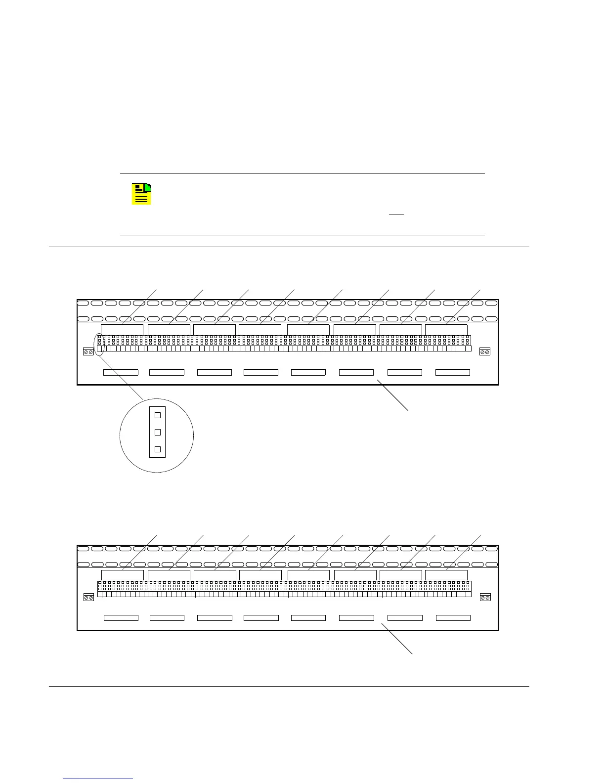
4.7.2 Timing Outputs
Connect the DS1 or composite clock outputs to the wirewrap pins on the
connection panel. Connect the tip wire to the pins labeled T, the ring wire to
the pins labeled R, and the shield to the pins labeled S. See Figure 4-15 for
the connections on 090-41902-01 wirewrap panels.
Figure 4-15. Timing Output Connections (090-41902-01) Wirewrap Panel
N
OTE
: The shield pin is provided to ground the cable shield at
the shelf, if required. Normally, the shield is grounded at the
source. Grounding the shield at both ends is not
recommended.
S
T
R
1
TO8 TO1TO2TO3TO4TO5TO7 TO6
123
456789
10
123
456789
10
123
456789
10
123
456789
10
123
456789
10
123
456789
10
123
456789
10
123
456789
10
Ports
A1–A10
Ports
A11–A20
Ports
A21–A30
Ports
A31–A40
Ports
B1–B10
Ports
B11–B20
Ports
B21–B30
Ports
B31–B40
TO8 TO1TO2TO3TO4TO5TO7 TO6
123
456789
10
123
456789
10
123
456789
10
123
456789
10
123
456789
10
123
456789
10
123
456789
10
123
456789
10
Ports
C1–C10
Ports
C11–C20
Ports
C21–C30
Ports
C31–C40
Ports
D1–D10
Ports
D11–D20
Not
Used
Not
Used
First Connection Panel
Second Connection Panel

 Loading...

