1
097-55501-01 Issue 6 – June 2003 57
2
5
3
Description
• Once the connectors have adequately engaged, tighten the screws
at top and bottom. This will ensure a good connection and
conductive seal around the module perimeter.
To remove an expansion output connector module:
• Loosen the screws at top and bottom of the module. Make sure that
they have actually released from the threads in the shelf.
• Grasping the now loosened screw heads, carefully rock the board
back off the module-to-shelf connector.
• As the board starts to release from the connector, the removal can
be completed by continuing to pull on the screw heads.
1.8 Relationship between Output Driver
Cards and Expansion Output Connector
Modules
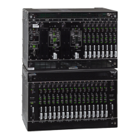
The key to understanding how the output driver cards (inserted on the front
of the shelf) relate to the output connector modules (attached on the rear of
the shelf) is to understand the meaning of the letter designations "A", "B", …
"H" which appear on labels on both sides of the shelf. An output driver card
inserted into a given letter category will have its outputs generated by output
connector modules that are attached to that same letter category on the
back of the shelf. So, for example, if an output driver card is inserted in
either slot of the "D" group, the output connector modules that will provide
output from that driver card will be found in the "D" group on the back of
the shelf. Another helpful thought is to think of the output driver cards
connecting to their associated output connector modules straight through
the shelf. Thinking this way, it is easy to see that the leftmost output driver
cards ("A" group looking at the front of the shelf) connect to the leftmost (still
looking at front of shelf) output connector modules.
There are two output connector module locations for each letter group. As
the labeling on the back of the shelf indicates, they are stacked vertically.
The upper (top) module provides outputs 1 through 20 for that particular
letter group, the lower module provides outputs 21 through 40 for that same
letter group. If 20 or fewer outputs of the same type are desired, there is no
need to load both output connector module locations.
The output driver cards (shelf front) have LEDs which indicate whether there
are associated output connector modules attached on the back of the shelf.
Indicators are provided for both ports 1 through 20 and 21 through 40. If
neither the CC nor DS1 LED is lit it means that there is no connector
module present in that location. Keep in mind that the purpose for having

 Loading...